Resistors in series and parallel, Kirchhoff's rules
Resistors in series and parallel
Problem:
Four identical light bulbs of resistance R are
connected as shown in the figure.
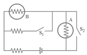
The battery provides a potential difference V0.
The switches S1 and S2 can be open and/or
closed in four different combinations: open-open, closed-closed, open-closed,
closed-open.
(a) Consider light bulb A: determine which
switch combinations would produce the brightest and dimmest light in bulb A.
(b) Consider light bulb B: determine which
switch combinations would produce the brightest and dimmest light in bulb B.
Solution:
- Concepts:
Resistors in series and parallel
- Reasoning:
Analyze a simple circuit.
- Details of the calculation:
(a) brightest:
S1 closed, S2
open, IA = 2V/(5R).
dimmest:
S2 closed, IA = 0.
(b) brightest:
S2 closed, S1
open, IB = V/(2R).
dimmest:
S1 closed, S2
open, IB = V/(5R).
Problem:
The
circuit shown in the diagram contains an ideal battery and two resistors, R1 and R2.
A voltmeter is used to measure the voltage across R1,
then across R2,
then across the battery.
Its readings are, respectively, 2.0 V; 3.0 V; 6.0 V.
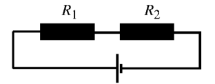
What are the actual voltages across the resistors?
Solution:
- Concepts:
Resistors in series and parallel
- Reasoning:
The voltmeter as has a shunt resistance R. It reads the voltage across
this resistance. When placed in a circuit, it correctly reads the
battery voltage but not the voltages across the resistors of the undisturbed
circuit.
The battery voltage is V = 6 V.
The voltages across R1 and R2 (without the voltmeter
in the circuit) are
V1 = 6V R1/(R1 + R2) and V2
= 6V R2/(R1 + R2), respectively.
V1 = 6V /(1 + R2/R1), V2 = 6V /(1 +
R1/R2).
We need to solve for the ratio R1/R2.
- Details of the calculation:
With the voltmeter in the circuit we have:
2V = 6V [R1R/(R1 + R)]/[ (R1R/(R1 +
R)) + R2] or 2V = 6V/[1 + R2(R1 + R)/(R1R)]
3V = 6V [R2R/(R2 + R)]/[ (R2R/(R2 +
R)) + R1] or 3V = 6V/[1 + R1(R2 + R)/(R2R)]
[1 + R2(R1 + R)/(R1R)] = 3, R2(R1
+ R)/(R1R) = 2, R2/R + R2/R1 = 2,
1/R = 2/R2 - 1/R1
[1 + R1(R2 + R)/(R2R)] = 2, R1(R2
+ R)/(R2R) = 1, R1/R + R1/R2 = 1.
1/R = 1/R1 - 1/R2
Therefore 3/R2 = 2/R1, R1/R2 =
(2/3).
V1 = 6V *2/5 = 2.4 V, V2 = 6V*3/5 = 3.6 V.
Problem:
What is the
resistance of the following network? Each ohmic resistor has resistance R.
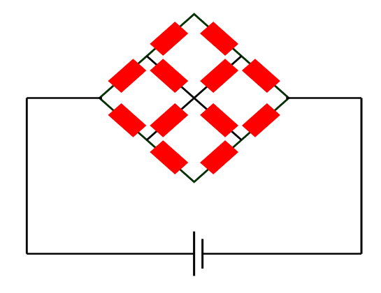
Solution:
- Concepts:
Resistors in series and parallel
- Reasoning:
The circuit has enough symmetry so that we can analyze it like a simple
circuit with resistors in series and parallel.
- Details of the calculation:
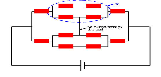
Rtotal = (3/2)R.
Problem:
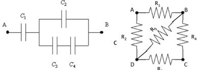
(a) Four capacitors are connected as shown in the figure.
C1 = C2 = C3 = C4 = 1
μF.
What is the total capacitance between points A and B?
(b) Five identical 1 Ω resistors are joined and form the four sides of square
and its diagonal. What is the resistance between points A and B?
Solution:
- Concepts:
Capacitors and resistors in series and parallel
- Reasoning:
We are asked to find the effective capacitance and resistance of given
configurations.
- Details of the calculation:
(a) The inverse of the equivalent capacitance for the
sub-circuit with two capacitors C3 and C4 is
1/Ceq = 1/1 + 1/1 = 2, thus Ceq= ½. Now, the
equivalent capacitance for the sub-circuit with C2, C3,
and C4 is Ceq'= C + Ceq = 1 + ½ = 3/2.
Finally, the equivalent capacitance for the entire circuit is 1/Ceq''
= 1/C1 + 1/Ceq' = 1 + (2/3) = 5/3, thus Ceq''=
3/5. The total capacitance is 0.6 uF.
(b) The equivalent resistance of a sub-circuit with R3
and R4 is 2. The equivalent resistance of a sub-circuit with R3,
R4, and R5 is 1/Req =1/1 + ½ = 3/2, thus Req
= (2/3). The equivalent resistance of a sub-circuit with R2, R3,
R4, and R5 is Req' = R2 + Req
= 1 + (2/3) = 5/3. Finally, the equivalent resistance of the entire circuit is 1/Req''=
1/1 + 3/5 = 8/5, thus Req''= 5 /8. The resistance between points A
and B is 5/8 Ω.
Problem:
Find the maximum power of a
heating element that can be constructed from a piece of wire
that has a resistance of 536 Ω. The element is to be powered
by a constant voltage of V = 110V. The current through the wire
cannot exceed 2.0 A.
(a) Assume that you are
allowed to discard a section of the wire,
(b) Assume that you are NOT allowed to discard a section of the wire,
Solution:
- Concepts:
Ohm's law, I = V/R, Power P = IV, resistors in
series and parallel
- Reasoning:
We can cut the wire into N pieces and connect these pieces in parallel to the
power supply.
- Details of the calculation:
Since V is constant, we have to maximize I to maximize P.
For each of the pieces of wire that are connected in parallel we have
I = V/R, Imax = 2 A = 110 V /Rmin, Rmin = 55
Ω.
(a) We can cut 9 pieces of 55 Ω and discard one piece of 41 Ω.
Then the total current is 9*2 A and the power dissipated
is 1980 W.
(b) We can cut 8 pieces of 55 Ω and 1 piece of 96 Ω. The total current them is
Itotal = 8*110 V/(55 Ω) + 110 V/(96 Ω). The power is P = VItotal
= 1886 W.
But what if we cut some small piece of the 96 Ω wire and added it to one of the
55 Ω wires?
I = V/R, dI = -(V/R2)dR
The total change in current through the wires them is dI = -(V/R255Ω)dR
+ (V/R296Ω)dR.
dI is negative, less current flows, less power is dissipated in the heating
element. The maximum power dissipated in the heating
element is 1886W.
Problem:
In the
infinite circuit shown in the diagram, each battery has emf ε and internal
resistance r. Each resistor has resistance 2r. Find the emf and the internal
resistance of the equivalent battery.

Solution:
- Concepts:
An
infinite ladder network
- Reasoning:
Since the ladder is infinite, the current through the equivalent emf and
internal resistance will not
change if an additional section is added to the front of ladder.
- Details of the calculation:
Any combination of batteries and resistances with two terminals can be
replaced by a single voltage source V and a single series resistor R. The
Thevenin voltage V is an ideal voltage source equal to the open circuit
voltage at the terminals. The Thevenin resistance R is the resistance
measured at the terminals with all voltage sources replaced by short
circuits and all current sources replaced by open circuits. Let the
Thevenin voltage of the network be V am let the Thevenin resistance be R.
The network is made of an infinite number of sections.
Let us construct a new two-terminal network by adding another section to the
front of the old two-terminal network.
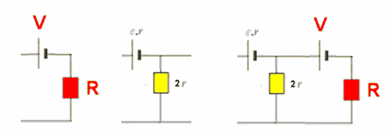
Let the Thevenin voltage of the new network be V' and let the Thevenin
resistance be R'.
We have
V' = ε +V2r/(2r + R), R' = 2rR/(R + 2r) + r = (3rR + 2r2)/(R
+ 2r).
Setting R' = R, V' = V we obtain
R2 - rR - 2r2 = 0, R = r/2 + ((r/2)2 + 2r2)½
= 2r.
V = (2r + R)ε/R = 2ε.
The emf of the equivalent battery is 2ε, and the internal resistance is 2r.
Problem:
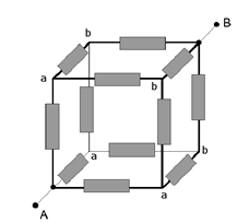
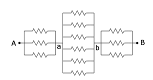
(a) Calculate the resistance between two points A
and B of the infinite system of resistors.
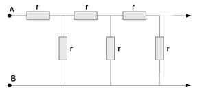
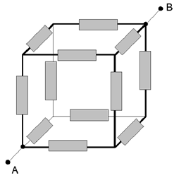
(b) Calculate the resistance between points A and
B of the cube made of identical resistors r.
Solution:
Problem:
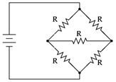
What is the equivalent resistance of the network shown? Each resistor has resistance R.
Solution:
- Concepts:
Resistors in series and parallel
- Reasoning:
No current flows through the center resistor. It can be ignored. Then circuit
has enough symmetry so that we can analyze it like a simple circuit with two
pairs of resistors in series. The pairs are parallel to each other.
- Details of the calculation:
For two resistors in series: Reff = R1 + R2.
For two resistors in parallel: 1/Reff = 1/R1 + 1/R2.
Each resistor has resistance R, the equivalent resistance is R.
Kirchhoff's rules
Problem:
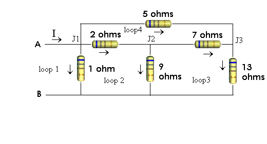
Find the equivalent resistance between the points A and B of the circuit
shown in the figure below.
Solution:
Problem:
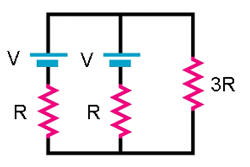
In the circuit above,
express the current in the 3R resistor in terms of V and R.
Solution:
- Concepts:
Kirchhoff's rules
- Reasoning:
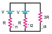
We can find the currents I1, I2, and I3
using Kirchhoff's rules. The junction rule states that the sum of the
currents entering a junction must equal the sum of the currents leaving that
junction. The loop rule states that the sum of the potential differences
around any closed circuit loop must be zero.
- Details of the calculation:
I1 + I2 = I3, I1 = I2,
V - 3RI3 - RI2 = 0. I3
= 2V/(7R).


