Circuits and non-conservative
fields
Problem:
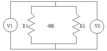
A closed loop shown in the figure below, with a cross
section of 0.1 m2, is placed in an external magnetic field changing
with time as B = kt, where k is equal to 1 T/sec. The magnetic flux is
confined to the region inside the loop. R1 has resistance of 3 Ω and R2 has resistance of 2
Ω. Calculate
(a) the value of the current I in the circuit, and
(b) the readings of the ideal voltmeters V1 and V2 and compare those values.

Solution:
- Concepts:
Faraday's law, conservative and non-conservative electric fields.
- Reasoning:
We are supposed to find the induced electric field. An induced field
is non-conservative.
- Details of the calculation:
(a) emf = -∂F/∂t.
F = BA, ∂F/∂t = A∂B/∂t
= 0.1 Tm2/s = 0.1 V.
I = emf/R = 0.1 V/(5 Ω) = 0.02 A.
(b) Both voltmeters reads zero. E is an induced field and not
conservative.
Problem:
(a) Assume
∂B/∂t = ∂B/∂t k for r < R and ∂B/∂t = 0
for r > R. Find the electric
field everywhere. Is E conservative?
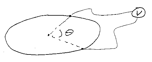
(b) Now assume a uniform, circular conducting ring, of radius R1 > R,
is placed in the field you found in (a), concentric with the origin. The
conductance of the ring is σ. Place voltmeter leads on the ring (see
figure below), separated by an angle θ. Plot the
reading of the voltmeter as a function of θ. Assume
an ideal voltmeter, with leads placed so that no flux cuts the circuit defined
by (leads + ring).

Solution:
- Concepts:
Faraday's law, conservative and non-conservative electric fields.
- Reasoning:
We are supposed to find the induced electric field. An induced field
is non-conservative.
- Details of the calculation:
(a) ∇×E = -∂B/∂t, ∮Γ E∙dr = -∂/∂t∫AB∙n
dA, ε = -∂F/∂t.
For the flux F of the magnetic field through a ring of radius r
perpendicular to and centered on the z-axis we have
∂F/∂t = 2πrE = -πr2∂B/∂t
for r < R, ∂F/∂t = 2πrE
= -πR2∂B/∂t
for r > R.
(Note: r is a cylindrical coordinate here.)
E = -(φ/φ)(r/2)∂B/∂t
for r < R, E = -(φ/φ)(R2/(2r))∂B/∂t
for r > R.
E is an induced field and not conservative.
(b) In the ring we have
E = -(φ/φ)[R2/(2R1)]∂B/∂t.
E + ∂A/∂t = -∇Φ.
B = ∇×A,
B = B
k
for r < R, B = constant for r > R. For simplicity choose the
constant to be zero.
Let A = Aφ(r)(φ/φ),
then B = (1/r)(∂/∂r)(rAφ(r))
for r < R, Aφ(r) = Br/2.
For r > R, 0 = (1/r)(∂/∂r)(rAφ(r)),
Aφ(r) = const/r.
Since Aφ(r) is continuous, const = BR2/2.
At r = R1 we have Aφ(R1)
= BR2/(2R1), ∂Aφ(r)/∂t|R1 = (∂B/∂t)R2/(2R1).
E + ∂A/∂t = 0,
∇Φ = 0. V = constant, ∆V = 0.
The ideal voltmeter reads zero, independent of the angle θ.
Problem:
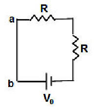
Consider the square circuit shown in the figure below, with
a battery with potential V0 = 1.5 V and two identical resistors with
R = 1 kΩ. Each side of the square has
a length of 50 cm.

(a) Find the
current I0 flowing in the
circuit. Determine the potential of point a with respect to point b, i.e. Vab.
Does
∫abE∙dr
depend
on what path you take along the circuit?
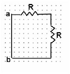
(b) Now consider the same circuit but without the battery. A
uniform magnetic field of magnitude B0 is perpendicular to the plane
of the circuit and points out of the page. The circuit cannot be moved or
deformed.

At what rate (magnitude and direction) does B have to
change to produce the same current I0 as in the circuit in part (a)?
(c) When a current I0 is flowing in the circuit in part (b),
does
∫abE∙dr depend
on what path you take along the circuit? Explain!
Solution:
- Concepts:
Faraday's law, conservative and non-conservative
electric fields.
- Reasoning:
An induced field is a non-conservative field.
- Details of the calculation:
(a)
I0 = (1.5 V)/(2*103 Ω)
= 0.75 mA. Vab = 0. ∫abE∙dr
= Vab = 0.
It does not depend on the path.
(b) (dB/dt)*(0.25 m2) =
1.5 V. dB/dt = 6 T/s. (dB/dt)
points out of the page. The magnitude of B is increasing.
(c)
The induced field is not a conservative field. A potential and
therefore a potential difference is only defined for a conservative field.
The potential difference Vab = 0.
∫abE∙dr depends on the path
along the circuit.
∫abE∙dr = 1.5
V ccw, ∫abE∙dr =
0 V cw.


