In this lab students will explore polarization effects. They will verify the Law of Malus and determine Brewster's angle for a microscope slide. They will also explore the properties of birefringent materials and construct an optical isolator.
![]()
Linearly polarized light is produced if the direction of E and the direction of propagation define a plane. The electric vector traces out a straight line. For example, E = Ei = E0xexp(i(kz - ωt))i.
The electric field vector E can always be resolved into two perpendicular components. If the light is linearly polarized, then the two components oscillate in phase. Ex = E0xexp(i(kz - ωt)), Ey = E0yexp(i(kz - ωt)). If it is elliptically polarized, the two components have a constant phase difference, and the tip of the electric field vector traces out an ellipse in the plane perpendicular to the direction of propagation. Ex = E0xexp(i(kz - ωt)), Ey = E0yexp(i(kz - ωt + φ)).
Circularly polarized light is a special case of elliptically polarized light in which E0x = E0y and the two components have a 90° phase difference and the electric field vector traces out a circle in the plane perpendicular to the direction of propagation. When viewed looking towards the source, a right circularly polarized beam has a field vector that describes a clockwise circle (φ = -π/2), while left circularly polarized light has a field vector that describes a counter-clockwise circle (φ = π/2).
![]()
Let Ex = E0xexp(i(kz - ωt)), Ey = E0yexp(i(kz - ωt + φ)).
| Linearly polarized light: φ = nπ, n = 0, 1, 2, ... | |
| Circularly polarized light: E0x = E0y, φ = nπ/2, n = 1, 3, 5, ... | |
| Elliptically polarized light: φ = arbitrary, but constant. | |
| Unpolarized light: φ, Ey, Ex are randomly varying on a timescale that is much shorter than that needed for observation. |
![]()
Polarization Mechanisms
Dichroism: Certain naturally occurring crystalline materials have transmittance properties which depend on the polarization state of light. The most common method of producing polarized light is to use polaroid material, made from chains of organic molecules, which are anisotropic in shape. Light transmitted is linearly polarized perpendicular to the direction of the chains. If linearly polarized light passes through polaroid material, then the transmitted intensity is given by It = I0cos2θ, (Law of Malus), where θ is the angle between E and transmission direction.
Reflection: When unpolarized light is incident on a boundary between two dielectric surfaces, for example on an air-glass boundary, then the reflected and transmitted components are partially plane polarized. The reflected wave is 100% linearly polarized when the incident angle is equal to the Brewster angle θB. We then have tanθB = n2/n1.
Birefringence (double refraction): Certain crystalline substances have a refractive index which depends upon the state of incident polarization. Unpolarized light entering a birefringent crystal not along the optic axis of the crystal is split into beams which are refracted by different amounts.
| Linearly birefringent, uniaxial crystalline materials are characterized by having a unique axis of symmetry, called the optic axis, which imposes constraints upon the propagation of light beams within the crystal. Two modes are permitted, either as an ordinary beam polarized in a plane normal to the optic axis, or as an extraordinary beam polarized in a plane containing the optic axis. Each of the beams has an associated refractive index. The two beams have different velocities and different angles of refraction in the crystal. The direction of the lesser index is called the fast axis because light polarized in that direction has the higher speed. Suitably cut and oriented prisms of birefringent materials can act as polarizers and polarizing beam splitters. | |
| A thin plate of birefringent crystal of thickness d cut parallel to the optic axis is known as a wave plate. Assume linearly polarized light is entering the wave plate normally. The components of E parallel and perpendicular to optic axis emerge with a phase difference d between them given by δ = (2πd/λ)Δn. | |
| A quarter-wave plate δ = π/2 can be used to convert linearly polarized light to circularly polarized light. The incident linearly polarized light must be oriented at 45o to the wave plate's axes. | |
| A half-wave plate δ = π can be used to rotate the plane of linearly polarized light. The angle of rotation is 2θ, where θ is the angle between the angle of polarization and the wave plate's fast axis. | |
| If a plane polarized beam propagates down the optic axis of a material exhibiting circular birefringence it is resolved into two collinear circularly polarized beams, each propagating with a slightly different velocity. When these two components emerge from the material, they recombine into a plane polarized beam whose plane of polarization is rotated from that of the incident beam. This effect of producing a progressive rotation of the plane of polarization with path length is called optical activity, and is used to produce optical rotators. |
![]()
|
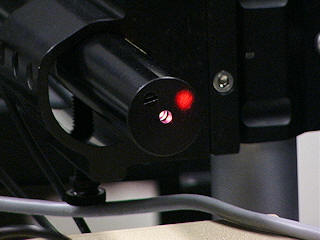
Laser Assembly | |
|
Beam Steering Assemblies | |
|
Lens Chuck Assemblies | |
|
Rotation Stage Assembly | |
|
Target Assemblies | |
|
Beam Splitter | |
Linear Polarizers | |
|
Quarter Wave Plate | |
|
Laser Power Meter | |
|
Project in Optics Workbook |
![]()
Part I: Verify the Law of Malus
Follow the instructions on pages 75 - 78 (Polarization of Light)
of the Projects in
Optics Workbook. Complete Steps 1 - 6. Fill in the table below
and plot your results.
Note: Our polarizers are mounted in rotation stages. The
transmission axis is not marked..
| θ(deg) | 0 | 10 | 20 | 30 | 40 | 50 | 60 | 70 | 80 | 90 | 100 | 110 | 120 | 130 | 140 | 150 | 160 | 170 | 180 |
| It/Io |
Part II: Polarization by reflection
Complete steps 7 - 12.
Hints: Fix the rotation stage at 0o (tighten the lock screw) and mount the glass slide onto the rotation stage. The surface of the slide is vertical. Rotate the slide until the light reflecting off the slide reflects back onto itself, and then tighten the slight in the post holder.
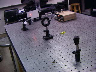
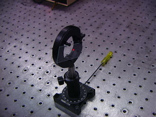
The Brewster angle for reflecting off glass is between 50o and 60o. Loosen the lock screw on the rotation stage and rotate the slide approximately 55o. Follow the reflected beam and make it pass through a polarizer onto an index card. At the Brewster angle the reflected beam should be 100% vertically polarized. A polarizer with a horizontal transmission axis should block it completely. (Set the rotation angle for the rotation stage holding the polarizer to ~90o to get a horizontal transmission axis.) Make fine adjustments to the angles of the rotation stages for the slide and the polarizer until the reflected light is completely blocked. Looking through the polarizer from the other side, you will not see the reflected beam, you have completely blocked the glare from the reflected light.
Measure Brewster's angle and use this measured value to find the index of refraction of the microscope slide. Is this value reasonable?
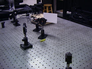
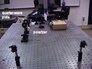
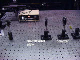
Part III: An Optical Isolator
(a) Follow the instructions on pages 79 - 81 of the Projects in Optics Workbook. Complete Steps 1 - 10. Verify that the quarter-wave plate produces circularly polarized light.
Hints: You can leave out the beam splitter and observe reflected beam hit the face of the laser next to the beam exit hole.
Place a polarizer with a vertical transmission axis into the path of the laser. You should still see the reflected beam hit the face of the laser.
(b) Complete steps 11 - 13. Verify that you have produced an optical isolator in step 11. Verify that the half-wave plate rotates the input polarization by 90o.
Hints: Place a quarter-wave plate with one of its axes vertical between the polarizer and the last mirror. The quarter-wave plate is mounted in a rotation stage. When the rotation angle is ~0o one of the axes is vertical. You should still see the reflected beam hit the face of the laser.
Rotate the axis of the quarter-wave plate by ~45o. The vertically polarized light incident on the last mirror will be converted to circularly polarized light as it passes through the quarter-wave plate and converted into horizontally polarized light after reflection, as it passes through the quarter-wave plate again. It now will be blocked by the polarizer. You should no longer see the reflected beam hit the face of the laser. (Make fine adjustments until the spot disappears.)
![]()
Open Microsoft Word and prepare a report using the template shown below.
| In a few words, describe the experiment. (What?) | |
| In a few words, state the objective of the experiment. (Why?) | |
| Comment on the procedure. Did you encounter difficulties or surprises? (How?) | |
| Present your results and comment on your results. |