In this lab students will build a Twyman-Green interferometer. They will then use the interferometer to test a plane parallel glass plate and a microscope cover slip for refractive index and thickness variations.
![]()
|
Laser Assembly | |
|
Beam Steering Assemblies | |
|
Lens Chuck Assemblies | |
|
Target Assemblies | |
|
Lens Kit | |
|
Beam Splitter | |
|
Meter Stick | |
|
Index Cards | |
|
Project in Optics Workbook |
![]()
Follow the instructions on pages 67 - 70 of the Projects in Optics Workbook, but simplify the setup described in steps 1-8 by using the procedure described below..
| Turn on the laser. | |
| Reflect the laser beam from the middle of mirror 1 approximately 50 cm away from the output hole back onto the laser output hole. Use a mirror with a center-of-rotation adaptor so you later can turn it easily, and use a collar to fix the height of the mirror, so the height does not change when you loosen the screw in the post holder to turn the mirror. |
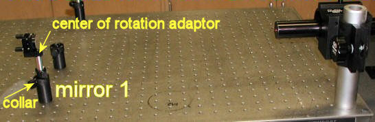
| Use lens paper in the beam path to observe the incident as well as the reflected beam and adjust the mirror so that the reflected beam overlaps the incident beam. |
|
(Optional) Insert a beam expander between mirror 1 and the laser. For example, a 200 mm lens and a 25 mm lens to expand the beam by a factor of 8.
| |
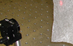
| Mount the beam splitter approximately 6 inches from mirror 1 at a right angle to the laser - mirror 1 line, and mount each of the other two mirrors without center-of-rotation adaptors approximately 8 inches from the beam splitter as shown in the figure below. |
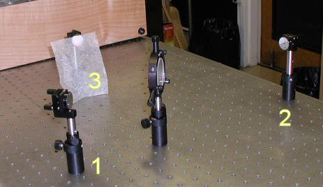
| Rotate mirror 1 so that one of the laser beams strikes the center of mirror 2, and then rotate the beam splitter so that the other laser beam strikes the center of mirror 3. | |
| Cover mirror 3 with an index card and adjust mirror 2, so that the laser beam reflects from mirror 2 back onto the laser just above the output hole. Use lens paper to help you view the reflected beam. | |
| Cover mirror 2 with an index card and adjust mirror 3, so that the laser beam reflects from mirror 3 back onto the laser just above the output hole. | |
| Uncover both mirror and observe fringes on an index card. Magnify the fringes using a lens. |
|
Complete steps 9 and 10 as described in the workbook. Adjust the test mirror to observe fringes of equal thickness on the observation screen.
Measure the separation between the fringes and record the
spacing between two successive fringes.
| |
| Observe how the fringe pattern changes when you push lightly against the post holder for one of the mirrors. Every relative movement of 1/4 wavelength (1/4 *633 nm) will change a bright fringe into a dark fringe and vice versa. | |
| Insert a glass slide or a piece of plastic into one of the paths.
observe changes in the fringe pattern.
|
| The fringes, being lines of equal phase difference, are actually a contour
map of the distorted wave front. Imperfections of the sample show up
in terms of wave front aberrations. Do you observe imperfections? If
so, estimate the magnitude of the optical path length variations in the
glass slide. Repeat this experiment replacing the glass slide with a microscope cover slip. |
Part II
|
Complete steps 11 and 13 as described in the workbook. Describe your observation for each step, and if necessary, make sketches. |
![]()
Open Microsoft Word and prepare a report using the template shown below.
| In a few words, describe the experiment. (What?) | |
| In a few words, state the objective of the experiment. (Why?) | |
| Comment on the procedure. Did you encounter difficulties or surprises? (How?) | |
| Present your results and comment on your results. |