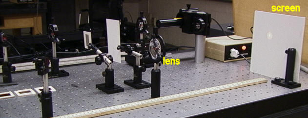
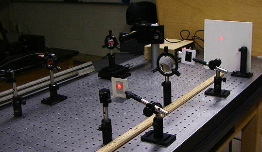
In this lab students will build a single-lens, coherent light optical processor and use it to explore the effect of various spatial filters on the image of a square mesh.
![]()
When an expanded laser beam illuminates a slide, the light will diffract and the spectrum of spatial frequencies will be displayed in the back focal plane of the lens (the frequency plane). The light pattern in the back focal plane describes the content of spatial frequencies found in the slide. Patterns that are large and smoothly varying in their shading represent low spatial frequencies and will not diffract the beam much. Their contributions will lie close to the optical axis in the focal plane of the lens. Patterns that are small or have fine details and sharp edges will cause a substantial amount of diffraction and their contributions will lie further from the optical axis in the frequency plane.
If the slide contains a fine, square wire mesh, then the the spatial frequencies are represented by a two-dimensional grid of points in the frequency plane. The distance between neighboring wires determines the separation of neighboring points. If the slide is positioned more than one focal length from the lens, then a real image of the slide will be formed somewhere beyond the Fourier transform plane. In the Fourier transform plane larger spatial frequency appear at larger radii. Any intervention in that plane in the form of a mask will change the distribution of spatial frequencies in the plane. It will also change the content of the image in the image plane in a predictable way. Modifying an image by changing its spatial frequencies contend is called spatial filtering.
A number of applications are based on this approach. The irradiance distribution of a laser beam in many lasers is Gaussian at the output mirror of the laser. Dust and small imperfections in the lenses, windows, and surfaces that the beam traverses or reflects off can produce irregularities in the irradiance pattern. The Gaussian distribution represents a low frequency spatial variation in the beam, whereas the irregularities contain higher spatial frequencies. If a small pinhole, with a diameter large enough to pass the low frequency Gaussian portion of the beam but small enough to block the high frequency part of the beam, is placed in the frequency plane, then the irregularities will be removed from the emerging beam and a “clean” laser beam will result.
![]()
|
Expanded laser beam | |
|
150 mm focal length converging lens | |
|
Object slides (grid, picture of astronaut) | |
|
Masks (slit, pinhole, black dot) | |
|
Screen, index card | |
|
Meter Stick | |
|
Project in Optics Workbook |
![]()
Follow the instructions on pages 82 - 85 of the Projects in Optics Workbook.
|
Direct the expanded laser beam through the center of the 150 mm focal length converging lens onto the screen. |
|
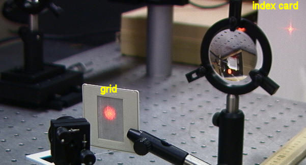
Place the object slide with the grid into the beam, ~22.5 cm in front of the lens. Observe the image of the grid on the screen, ~45 cm behind the lens. Make sure the gridlines are horizontal and vertical. | |
|
Place an index card ~15 cm behind the lens and observe the Fourier transform of the grid. Translate the index card until you have the sharpest image of the Fourier transform. You should see a pattern of dots (vertical and horizontal) with a central bright spot. |

|
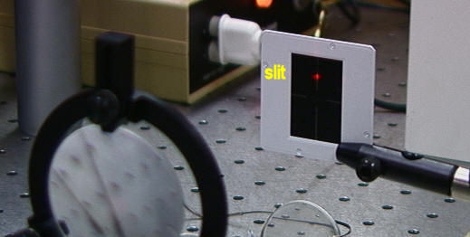
Remove the index card and replace it with a dark slide with slits. Place the slit over the Fourier transform pattern such that only light from the dots along the vertical symmetry axis passes through the slit. Examine the image on the screen. You should see that the image consists of only horizontal lines. You have smoothed out all the vertical lines by removing the high frequency content in the Fourier transform that produced the sharp features of these lines. |
| Now place the slit over the Fourier transform pattern such that only light from the dots along the horizontal symmetry axis passes through the slit. Examine the image on the index card. What do you observe on the screen? | |
| Replace the slit with a 0.5 mm diameter pinhole. Let only light from the central bright spot pass through the pinhole. Make sure that the pinhole is at the position where this spot has its smallest size. What do you observe on the screen? | |
|
Replace the grid slide with a slide containing the picture of an astronaut. | |
|
Observe the image of some region with well defined edges (for example the backpack) on the screen. Observe the Fourier transform of the astronaut picture. It does not appear as regular as the Fourier transform of the grid, but it also has a central bright spot. Cover the bright spot with a black dot. Make sure you do that at the position where the bright spot has its smallest size. Do you observe edge enhancement on the screen? |
Describe all your observations and make sketches of the observed patterns.
![]()
Open Microsoft Word and prepare a report using the template shown below.
| In a few words, describe the experiment. (What?) | |
| In a few words, state the objective of the experiment. (Why?) | |
| Comment on the procedure. Did you encounter difficulties or surprises? (How?) | |
| Present your results and comment on your results. |