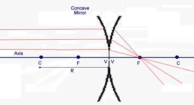

Mirrors can form images. In the paraxial approximation we can derive the mirror equation for convex and concave spherical mirrors using the law of reflection. We now want to treat reflecting surfaces using matrix methods. But we have be careful. In the case of refraction, rays that move from left to right continue to move from left to right after refraction but in the case of reflection their course is reversed. After reflection the rays move from right to left. Different books handle this problem in different ways.
We will adopt the following convention. We will keep the the sign convention for R from elementary optics. The mirror radius R is positive for a concave mirror and negative for a convex mirror. We will keep the optical axis going from left to right. We treat the rays after reflection as if they were proceeding from left to right like the incoming rays. We flip the optical axis. Of course, if we then calculate a positive image distance or a positive focal length, the image and the focus will actually lie to the left of the reference point in a traditional ray diagram.

The mirror matrix is then given by
 .
.
The distance from the vertex to the focal point is f = R/2.
![]()
A flat mirror
Let us trace a ray across a singe, flat reflecting surface at the origin. Let the index of refraction of the surrounding material be n = 1.
For a flat mirror R = infinite and
 .
.
Let the ray leave position (x1, z1) = (1 cm, -4 cm) making an angle θ1 = 0.1 radians with the z axis. What is its position (x3, z3) and angle θ3 after reflection when z3 is 4 cm?


We therefore have θ3 = 0.1 radians and x3 = 0.8 cm.
The matrix for the flat mirror is the identity matrix. When propagating rays through an optical system, we can ignore flat mirrors. They just change the direction of the optical axis.
To obtain an image with a flat mirror we need x3 to be independent of θ1. This happens if z3 = z1. Since z1 is negative z3 is negative, and in a conventional ray diagram the image lies behind the mirror. We have a virtual image.
![]()
For a spherical mirror we have


For image formation we need M21 = 0. This yields
1/(z2 - z1) + 1/(z3 - z2) = 2/R
When (z2 - z1) goes to infinity then 1/(z3 - z2) = 2/R =1/f.
Problem:
A concave mirror has a radius of 12 cm and an object 2 cm high is placed 24 cm to the left of the vertex V of the mirror. Where is the image formed and how large is it?
| Solution: For a concave mirror R and f are positive, R = 12 cm, f = 6 cm. Let the
vertex be at the origin. |
Problem:
A biconvex lens 2 cm thick with a radius of 6 cm is silvered on the second surface. The index of refraction of the lens material is 1.5. Where are the focal planes of this thick mirror?

|
Solution: |
We have refraction at V and reflection at V''.
The system matrix is (for refraction, translation, reflection, translation, refraction)
MVV' =
.
Inserting the given parameters we obtain
MVV' =
The position of the principal planes is D1 = D2 = -1.5 cm. The principal planes lie 1.5 cm behind of the vertex.
(D1 = n1(1-M11)/M12, D2 = n2(1-M22)/M12)
The focal points f1 = f2 = 1/(-M12) lie 1.841 cm on front of the principal plane and 0.341 cm in front of the vertex.
![]()
Reflection off Imperfect Plane Mirrors
In the real world, the description of light reflected off of a mirror or interface is more complicated than we have assumed.
| Mirrors do not have perfect surfaces, i.e. a flat mirror is not perfectly flat. | |
| Not all the incoming light is reflected, some may be transmitted through the mirror and some is absorbed by the mirror material. |
The surface of practical mirrors is not perfectly flat. Parallel rays therefore have different incident angles at different points on the surface and therefore are also reflected at different angles. The extreme cases are called perfect specular reflection, when all parallel rays are reflected at the same angle, and perfect diffuse reflection, when parallel rays are reflected randomly into different directions.
In practice we get both types of reflection. Rays that appears to obey the law of reflection when the angle of incidence is defined relative to the average surface normal are said to be specularly reflected, while rays that are reflected into random directions are said to be diffusely reflected.
For fully reflecting mirrors all light is either reflected or absorbed in the material of the mirror. No light is transmitted through the mirror. A good example of this type of mirror is a thick piece of metal. The more light is reflected and the less is absorbed, the better is the mirror.
Many mirrors are partially reflecting mirrors. The two main types of partially reflecting mirrors are partially silvered mirrors, which consist of a very thin metal film supported by a transparent (usually glass) substrate, and dielectric mirrors, which are simply plane interfaces between two materials of different refractive indices. The reflectance is determined by the thickness of the metal film in the first type, and by the difference between the refractive indexes in the second type.
Mirrors that are intentionally made to be partially reflecting are useful for splitting a beam of light into two components traveling into different directions (beam-splitters) and for one-way mirrors.