
| Two important aspects of any imaging system are the amount of radiation
passed by the system and the extent of an object that is seen by the system.
Stops and apertures limit the brightness of an image and the field of view of an
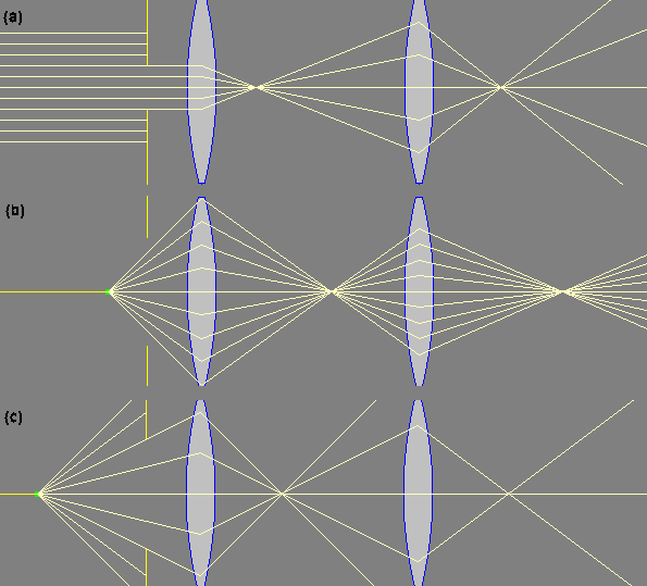
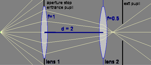
optical system. The aperture stop (AS) is defined to be the stop or lens ring, which physically limits the solid angle of rays passing through the system from an on-axis object point. The aperture stop limits the brightness of an image. For system (a) in the figure on the right the aperture is the aperture stop, for system (b) the first lens is the aperture stop and for system (c) the second lens is the aperture stop. The exit pupil is the image of the aperture stop formed by the light rays after they have passed through the optical system, i.e. it is the image of the aperture stop as seen through all the optics beyond the aperture stop. It can be a real or virtual image, depending on the location of the aperture stop. The entrance pupil is the opening an observer would identify as the limitation on the solid angle of rays diverging from an on-axis object point, i.e. it is the image of the aperture stop in as seen through all the optics before the aperture stop. Again, it can be a real or virtual image, depending on the location of the aperture stop.
Entrance and exit
pupils of two camera lenses |
 |
||||||||||
|
The following is simply a recipe for finding the aperture stop, entrance pupil, and exit pupil, given an optical system.
|
|||||||||||
The diagrams on the right shows two thin lenses with focal lengths f = 1 unit
and f
= 0.5 units, respectively, placed two units apart. The on-axis object is
located 1.5 units in front of the first lens.
|
 |
||||||||||
| In an optical system designed for visual observations, it is desirable to
have the exit pupil approximately coincide with the pupil of the observer’s
eye, since all the light from the object gathered by the optical system then
enters the eye. This is the origin of the term "pupil". Link:
|
|||||||||||
![]()
Field stop
For an off-axis object, the chief ray (CR) is the ray that passes through the center of the aperture stop. Rays that pass through the edge of the aperture stop are marginal rays (MR).
The aperture stop determines the solid angle of the transmitted light cone for an on-axis object. It limits the brightness of an image. The field stop determines the solid angle formed by chief rays from off-axis objects. It limits the field of view of an optical instrument. The image of the field stop as seen through all the optics before the field stop is called the entrance window. The image as seen through all the optics after the field stop is called the exit window.
The following is simply a recipe for finding the field stop, entrance window, and exit window, given a an optical system.
| Image all optical elements in the system into object space. | |
| Find the angle subtended by each image at the on-axis position of the entrance pupil. | |
| The element image with the smallest angle is the entrance window | |
| The physical object corresponding to this image is the field stop. | |
| The image of the field stop in image space is the exit window. |
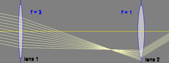
For the telescopic system shown on the right, the
object is very far away and the aperture stop and the entrance pupil are
lens 1.
A cone of light rays from an off-axis object to the entrance pupil will not necessarily be transmitted in its entirety. It can be partially cut off by field stops or lens rims in the system. This is called vignetting.
|
 |
|||||||||
|
Field of view The angular field of view is the angle formed by the edges of the entrance window at the on-axis position of the entrance pupil. For the telescopic system shown above, we find the location of the entrance window by finding the location of the image of lens 2 formed by lens 1. (1/4 + 1/xi = 1/3, xi = 12) The entrance window is located 12 units to the left of lens 1. Since the magnification is M = -3, the diameter of the entrance window is three times the diameter of lens 2. The entrance pupil is lens 1 itself. The half angle θ for the field of view is given by tanθ = 3*(radius of lens 2)/12. In a system with vignetting, the angular field of view may also be defined as the largest angle of an input chief ray with the optical axis.
|
||||||||||
| Problem: A telescope has the parameters listed
in the table on the right: |
|
|||||||||
|
 |
|||||||||
![]()
The human eye
| The simplest model of the human eye is a single lens
with an adjustable focal length that forms an image on the retina, or
the light-sensitive bed of nerves which lines the back of the eyeball.
The eye is either relaxed (in its normal state in which rays from
infinity are focused on the retina), or it is accommodating (adjusting
the focal length by flexing the eye muscles to image closer objects).
The near point of a human eye, defined to be s = 25 cm, is the shortest object distance that a typical eye is able to accommodate, or to image onto the retina.
|
|
| Myopia (nearsightedness)
In a nearsighted eye, the cornea is too steeply curved for the length of the eye, causing light rays from distant objects to focus in front of the retina. Distant objects appear blurred or fuzzy because the light rays are not in focus by the time they reach the retina. The eye is able to form images on the retina for objects that are closer than the eye’s far point. Myopia can be accommodated for through the use of a negative lens that will cause the light rays to diverge. The power of the lens is chosen by matching the lens’ focal point with the eye’s far point. |

|
| Hyperopia (farsightedness)
In contrast to myopia, hyperopia occurs when the eye is too short for the power of its optical components. In hyperopia, the cornea is not steep enough and light rays hit the retina before they come into focus. In the case of hyperopia, light from distant objects is focused to a point behind the retina. A positive lens can be used to correct for farsightedness. |
|
Focal Length and Diopters
When making and selling eyeglasses, people prefer to speak of the lens power P, measured in diopters D, instead of the focal length f. If you want to buy eyeglasses, you need to know the power of the lenses. Focal length and power of a lens are related to each other.
D = 1/f(m)
where
D = diopters, f = lens focal length (in meters), and a "+" sign indicates
a
converging lens and a "-" sign indicates a diverging lens.
For two thin lenses in contact, 1/f = 1/f1 + 1/f2, and therefore power is P = Pthin(1) + Pthin(2), i.e. the powers of thin lenses in contact add algebraically.
![]()
The Magnifying Glass and Angular Magnification
To make the image of a small object on the retina as large as possible, you must move the object as close to your eye as accommodation allows.
A magnifying glass enables you to enlarge the image on your retina even further. If you position the object less than or equal to one focal length fmag away from the magnifying glass, and if the glass is positioned close to your eye, a magnified virtual image is formed (at least 25 cm from your eye). The eye forms a magnified real image of this enlarged virtual image on the retina.
We define the angular magnification mα as the angle subtended by the virtual image (αi) divided by the angle subtended by the object when viewed with the unaided eye (αu).
mα = αi/αu
Here αi and αu are the angles made by the chief rays from the edge of the object with the optic axis in the case of the aided and unaided eye, respectively. The chief ray is the ray that passes through the center of the pupil.
A label such as "2X" or "10X" printed on a magnifying glass or an eyepiece belonging to a microscope or telescope indicates the angular magnification mα when the object is positioned at the focal length fmag of the magnifying glass, such that the virtual image is infinitely far away. This is called the magnifying power MP.
MP = (25 cm)/fmag.
|
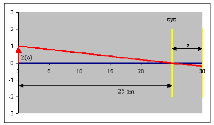
Example: In the figure on the right h(o) denote the height of the object and s the diameter of the eyeball. If the object is a distance of 25 cm from the eye, then the tangent of the angle made by the chief ray from the top of the object is tanθu= h(o)/25.
|
 |
|
With the object positioned at the focal length fmag of the magnifying glass, the tangent of the angle made by the chief ray is tanθi = h(o)/fmag. (Rays coming from a point in the object focal plane of a lens emerge as parallel rays from the other side of the lens. A ray entering parallel to the optic axis is deflected through the image focus.) This yields in the small angle approximation MP = θi/θu = (25 cm)/fmag. Placement of an object at the focal point of a magnifier or eyepiece is the ideal way to use these instruments, since the rays from the virtual image entering the eye are then parallel, and thus no accommodation is required to view the image on the retina. |
 |
![]()
Problem:
Assume that an eye can form an image of an object with object distance s on the retina (without glasses). Show that the lens equation for this eye may be written as
1/s = Pa + Pc,
where Pa is the power of accommodation and Pc is the refractive error, i.e. the amount by which the eye is too strong or too weak. Pc is positive for an eye with myopia or near-sightedness and negative for an eye with hyperopia or far-sightedness.
|
Solution: |
Problem:
A certain eye has 3D of myopia (nearsightedness) and 2D of accommodation.
(a) Find the near point (the shortest object distance for which the eye
can form an image) and the far point (the largest object distance for which the
eye can form an image).
(b) What are the near and far points if the myopia is corrected with a -3D
lens.
|
Solution:
(b) With correction we have for the near point 1/s
= Pa(max) = 2D, s = 50 cm. |