Light is a transverse electromagnetic wave. The electric field of an electromagnetic plane wave is of the form
E(r,t) = Emaxcos(k∙r -
ωt + φ),
Emax  k.
k.
The electric field of an EM plane wave traveling in the x-direction therefore may be written as
E(x,t) = Emaxcos(kx - ωt + φ),
Emax i.
If we consider a linearly polarized plane wave and we orient our coordinate system so that Emax is directed along the y-axis then we can drop the vector notation and write
E(x,t) = Emaxcos(kx - ωt + φ), E = Ey.
A more convenient notation is complex notation. For any angle θ,
cosθ = Re(exp(iθ)), exp(iθ) = cosθ + i sinθ.
We therefore rewrite the above equation as
E(x,t) = Emax exp(i(kx - ωt + φ)), E = Ey.
When we use complex notation to specify the electric field of an electromagnetic wave, it is implied that only the real part of the equation describes the electric field.
![]()
Two or more waves traveling in the same medium travel independently and can pass through each other. In regions where they overlap we only observe a single disturbance. We observe interference. When two or more light waves interfere, the resulting electric field amplitude is equal to the vector sum of the individual field amplitudes. If two waves with equal amplitudes are in phase and overlap i.e. if crest meets crest and trough meets trough, then we observe a resultant wave with twice the amplitude. We have constructive interference. If the two overlapping waves, however, are completely out of phase, i.e. if crest meets trough, then the two waves cancel each other out completely. We have destructive interference.
Let us add two linearly polarized plane electromagnetic waves with equal wavelengths but different phases, traveling along the x-axis.
E1(x,t) = A1 exp(i(kx - ωt + φ1)), E2(x,t) = A2 exp(i(kx - ωt + φ2)),
E(x,t) = E1(x,t) + E2(x,t) = (A1 exp(iφ1) + A2 exp(iφ2)) exp(i(kx - ωt))
= AR exp(i(kx - ωt + φR)).
The result of the addition is a linearly polarized plane electromagnetic waves with the same wavelength but a different phase and amplitude, traveling along the x-axis. Here AR is the resultant amplitude and φR is the resultant phase.
A1 exp(iφ1) + A2 exp(iφ2) = AR exp(iφR)
To find the magnitude of a complex number we multiply the number by its complex conjugate and then take the square root. The square of the resultant amplitude is given by
AR2 = (A1 exp(iφ1) + A2 exp(iφ2))(A1 exp(-iφ1) + A2 exp(-iφ2))
= A12 + A22 + A1A2(exp(i(φ1 - φ2)) + exp(-i(φ1 - φ2)))
= A12 + A22 + 2A1A2cos(φ 1- φ2).
The intensity of a wave is proportional to the square of its amplitude. The intensity of the resultant wave is therefore proportional to AR2.
| To find φR we use tanφR = (A1 sinφ1 + A2 sinφ2) / (A1 cosφ1 + A2 cosφ2). |
 |
![]()
Let us add two linearly polarized plane electromagnetic waves with equal amplitudes but slightly different wavelengths and therefore different frequencies. (ω/k = c/n.)
E1(x,t) = A exp(i(kx - ωt)), E2(x,t) = A exp(i((k + δk)x - ( ω + δω)t)),
E(x,t) = E1(x,t) + E2(x,t) = A exp(i(kx - ωt))(1 + exp(i(δk x - δω t)))
= A exp(i(kx - ωt)) exp((i/2)(δk x - δω t)) 2cos((δk x - δω t)/2)
= 2A exp(i((k + δk/2)x - (ω + δω/2)t)) cos((δk x - δω t)/2).
We obtain a traveling wave exp(i((k + δk/2)x - (ω + δω/2)t)) with the average frequency of the two waves being added, with an amplitude 2A cos((δk x - δω t)/2). The amplitude itself is a traveling wave, traveling with speed vg = δω/δk.
| We call vp = ω/k = c/n the phase
velocity of the waves and vg = δω/δk the group velocity. For electromagnetic waves in empty space vp
= vg = c. If we have dispersion in a material and the index of
refraction n = n(k), the the group and phase velocity are not equal to each
other. The two waves in the figure above have wavelengths of 20 and 21 units respectively. Their frequencies are v/20 and v/21, where v is the speed of the waves. The frequency of the intensity variations is v/20 – v/21 = v/420. |
 |
![]()
Double or multiple slit interference (interference by division of wave front)
The coherent sources for division of wave front interference are obtained by dividing a wave front originating from a single source. Double slit interference is an example of division of wave front interference.
Recall: We will observe constructively interference at certain angles. These angles are found by applying the condition for constructive interference, which is
d sinθ = mλ, m = 0, 1, 2, … .
where m is an integer, m = 1, 2, 3, ... .
![]()
Thin-film interference (interference by division of amplitude)
We can set up division of amplitude interference by dividing the amplitude of the incident beam is divided into two or more parts either by reflection, partial reflection or refraction.
| When the medium through which a wave travels abruptly
changes, the wave may be partially or totally reflected. When studying
mechanical waves we find that when a wave pulse traveling along a
rope reaches the end of the rope, it is totally reflected. The details
of the reflection depend on if the end of the rope is tied down and
fixed, or if it is allowed to swing loose.
A wave pulse, which is totally reflected from a rope with a fixed end is inverted upon reflection. The phase shift of the reflected wave with respect to the incident wave is π (180o).
|
|
| A wave pulse, which is totally reflected from a rope with a loose end is not inverted upon reflection. The phase shift of the reflected wave with respect to the incident wave is zero. When a periodic wave is totally reflected, then the incident wave and the reflected wave travel in the same medium in opposite directions and interfere. |
|
| We observe a similar phenomenon with light waves. When
a light wave reflects from a medium with a larger index of refraction,
then the phase shift of the reflected wave with respect to the incident
wave is π (180o). When a light wave reflects
from a medium with a smaller index of refraction, then the phase shift
of the reflected wave with respect to the incident wave is zero. The
reflected and the incident wave interfere.
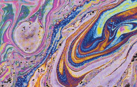
Constructive and destructive interference of reflected light waves causes the colorful patterns we often observe in thin films, such as soap bubbles and layers of oil on water. Thin-film interference is the interference of light waves reflecting off the top surface of a film with the waves reflecting from the bottom surface. If the thickness of the film is on the order of the wavelength of light, then colorful patterns can be obtained, as shown in the image on the right. |
 |
| Consider the case of a thin film of oil of thickness t
floating on water. For simplicity, assume that the light is incident
normally, so that the angle of incidence and the angle of reflection are
zero. In the air, the light reflecting off the air-oil interface will have a 180° phase shift with respect to the incident light. A 180o phase shift is equivalent to the light having traveled a distance of ½ wavelength. In the oil, the light reflecting from the oil-water interface will have no phase shift with respect to the light incident on the interface. For the light reflected off the oil and the light reflected off the water to constructively interfere we need the two reflected waves to have a phase shift of an integer multiple of 2π (360o). If the light reflected off the oil-water interface travels an additional distance equal to ½ the wavelength of the light in oil, then the total phase shift with respect to the light reflected off the air-oil interface will be 2π. This happens if the thickness of the film is equal to 1/4 the wavelength of the light in oil since the light has to traverse this thickness twice. We also get constructive interference if the thickness of the film is equal to 3/4, 5/4, ..., the wavelength of the light in oil. For constructive interference we need 2t = (m+½)λn, m = 0,1,2,…, where λn is the wavelength of the light in oil. |
|
In vacuum we have λf = c. In a medium with index of refraction n we have λnf = c/n. The frequency of oscillation is the same in vacuum and in a medium, therefore λn = λ/n. For constructive interference we therefore need
2 noil t = (m+½)λ, m = 0,1,2,….
Destructive interference occurs when the thickness of the oil film is equal to (½)λn, λn, (3/2)λn, etc.
For destructive interference we therefore need
2 noil t = mλ, m = 1,2,….
If the thickness of the film is (1/4)λn, the phase of the wave reflected off the top surface is shifted by π by the reflection. The phase of the wave traveling through the film is not shifted by reflection off the bottom surface, but the wave travels an extra distance of λn/2. It will therefore be in phase with the wave reflected off the top surface. If, on the other hand, the film thickness is ½λn, then the wave traveling through the film travels an extra distance of 1 wavelength. It will therefore be out of phase with the wave reflected off the top surface and the two waves will cancel each other out.
| Waves incident at an angle θi on the air oil
interface are refracted as they enter the oil. The angle of refraction θt
is found from Snell's law, nairsinθi = noilsinθt. If they are reflected off the second interface, then they travel a
distance 2t/cosθt in the oil. When they emerge again from the
oil into the air and propagate parallel to the waves reflected at the
air-oil interface, then the total optical path length difference is
2 noil t/cosθt - 2d tanθtsinθi = 2 noil t/cosθt - 2d tanθt(noil/nair)sinθt = 2noilt/cosθt(1 - sin2θt) = 2 noil t cosθt. For constructive interference we therefore need 2 noiltcosθt = (m+½)λ, m = 0,1,2,…, and for destructive interference we need 2 noil t cosθt = mλ, m = 1,2,…. Constructive and destructive interference occur at different angles for different wavelength. The observer sees colored bands. |
 |
The destructive interference of reflected light waves is utilized to make non-reflective coatings. Such coatings are commonly found on camera lenses and binocular lenses, and often have a bluish tint. The coating is put over glass, and the coating material generally has an index of refraction less than that of glass. Then the phase shift of both reflected waves is 180°, and a film thickness equal to 1/4 of the wavelength of light in the film produces a net shift of ½ wavelength, resulting in cancellation. For such non-reflective coatings the minimum film thickness t required is
t = λ/4n,
where n is the index of refraction of the coating material. A coating with thickness t = λ/4n prevents the reflection of most of the light with a wavelength λ close to λ = 4nt. The coating does not reflect a specific range of wavelengths. Often that range is chosen to be in the yellow-green region of the spectrum, where the eye is most sensitive. Lenses coated for the yellow-green region reflect in the blue and red regions, giving the surface a familiar purple color.
Problem:
When sunlight reflects from a thin film of soapy water, the film appears multicolored, in part because destructive interference removes different wavelengths from the light reflected at different places, depending on the thickness of the film. As the film becomes thinner and thinner, it looks darker and darker in reflected light, appearing black just before it breaks. The blackness means that destructive interference removes all wavelengths from the reflected light when the film is very thin. Explain!
| Solution: The phase shift of a ray in air reflecting from the air-film interface is π. The phase shift of a ray traveling through the film and reflecting from the film-air interface is zero. As the film gets thinner, most of the phase difference between the two reflected rays is due to π radians phase shift during the reflection off the air-film interface. This phase shift is the same for all wavelengths, and results in destructive interference. |
Problem:
A thin film of a material is floating on water (n = 1.33). When the material has a refractive index of n = 1.20, the film looks bright in reflected light as its thickness approaches zero. But when the material has a refractive index of n = 1.45, the film looks black in reflected light as the thickness approaches zero. Explain these observations in terms of constructive and destructive interference and the phase changes that occur when light waves undergo reflection.
| Solution: If the refractive index of the film is greater than that of the water below, the phase shift of the ray traveling through the film and reflecting off the interface between the film and the water is zero. We have the same situation as in the previous problem. If the refractive index of the film is less than that of water the phase shift of the ray traveling through the film and reflecting off the interface between the film and the water is π. Both reflected rays now have the same phase. As the film thickness approaches zero, they are in phase and the material will look bright. |