The electric field vector E can always be resolved into two perpendicular components. The light is elliptically polarized, then the two components have a constant phase difference, and the tip of the electric field vector traces out an ellipse in the plane perpendicular to the direction of propagation.
Ex = E0xexp(i(kz - ωt)), Ey = E0yexp(i(kz - ωt + φ)).
Linearly polarized light is a special case of elliptically polarized light. If the light is linearly polarized, then the two components oscillate in phase, for example Ex = E0xexp(i(kz - ωt)), Ey = E0yexp(i(kz - ωt)), φ = 0. The direction of E and the direction of propagation define a plane. The electric vector traces out a straight line. For example, E = Ei = E0xexp(i(kz - ωt))i.
| Circularly polarized light is also a special case of elliptically polarized light
in which E0x = E0y and the two components have a 90° phase
difference and the electric field vector traces out a circle in the plane
perpendicular to the direction of propagation. When viewed looking towards
the source, a right circularly polarized beam has a field vector that describes
a clockwise circle (φ = -π/2), while left
circularly polarized light has a field vector that describes a counter-clockwise circle
(φ = π/2) at a fixed position z. The figure below shows the trace of the field vector Ex = E0exp(i(kz - ωt)), Ey = E0exp(i(kz - ωt + φ)) in a plane perpendicular to the z-axis when looking towards the source. (E0x = E0y = E0) |
 |
 |
 |
 |
 |
| φ = 0 Ex = cos(ωt) Ey = cos(ωt) |
φ = π/4 Ex = cos(ωt) Ey = cos(ωt - π/4) |
φ = π/2 Ex = cos(ωt) Ey = cos(ωt - π/2) = sin(ωt) |
φ = 3π/4 Ex = cos(ωt) Ey = cos(ωt - 3π/2) |
 |
 |
 |
 |
| φ = π Ex = cos(ωt) Ey = cos(ωt - π) = -cos(ωt) |
φ = 5π/4 Ex = cos(ωt) Ey = cos(ωt - 5π/4) |
φ = 3π/2 Ex = cos(ωt) Ey = cos(ωt - 3π/2) = -sin(ωt) |
φ = 7π/4 Ex = cos(ωt) Ey = cos(ωt - 7π/4) |
You can also open the spreadsheet and explore.
![]()
| Let Ex = E0xexp(i(kz - ωt)),
Ey = E0yexp(i(kz - ωt + φ)).
|
Unpolarized light:
|
![]()
Polarization Mechanisms
| Dichroism: Certain naturally occurring crystalline materials have transmittance properties which depend on the polarization state of light. Dichroism is the selective absorption of one plane of polarization in preference to the other, orthogonal polarization during transmission through the material. The most common method of producing polarized light is to use polaroid material, made from chains of organic molecules, which are anisotropic in shape. Light transmitted is linearly polarized perpendicular to the direction of the chains. If linearly polarized light passes through polaroid material, then the transmitted intensity is given by It = I0cos2θ, (Law of Malus), where θ is the angle between E and transmission direction. If θ = 90o the transmitted intensity is zero. |
|
| A polarizer produces linearly polarized light. It is often convenient to orient the transmission axis of a polarizer vertically or horizontally to produce light with vertical or horizontal linear polarization. |
 Vertical and horizontal polarization |
| Reflection: When unpolarized light is incident on a boundary
between two dielectric surfaces, for example on an air-glass boundary, then the
reflected and transmitted components are partially plane polarized. The Fresnel
reflection coefficients are different for p- and s-polarized light. The
reflected wave is 100% linearly polarized when the incident angle is equal to
the Brewster angle θB.
We then have tanθB = n2/n1. When the sun is at a low angle in the sky, the sunlight reflecting off the surface of water is nearly 100% horizontally polarized because the angle of incidence is close to the Brewster angle. Glare-reducing sunglasses are coated with a polarizer with a vertical transmission axis and therefore block the reflected light. |
|
| If a number of plates are stacked parallel to one another, and the entire
pile is oriented at the Brewster angle, some of the s-polarized light will
be reflected and all of the p-polarized light will be refracted at each
interface. After one interface the refracted beam will be partially
polarized, having lost some of its s-polarized component. If the stack
contains many plates, then the refracted beam will have a high degree of
polarization, since at each interface the same fraction of the remaining
s-polarization is lost. This pile-of-plates polarization mechanism is
used in many polarizing beam splitters, where many layers of dielectric thin
film are laid onto the interior prism angle of the beam splitter. Link: Brewster angle |
|
| Birefringence (double refraction): Certain crystalline substances have a refractive index which depends upon the state of incident polarization. Unpolarized light entering a birefringent crystal not along the optic axis of the crystal is split into beams which are refracted by different amounts. |
 |
 |
 |
 |
| Double refraction in a calcite crystal. The
vertical lines are imaged twice. The polarization of the light producing one image is perpendicular to the polarization of the light producing the other image. |
||
| A linearly birefringent crystal, such as calcite, will divide an entering beam of monochromatic light into two beams having orthogonal polarizations. The beams will usually propagate in different directions and have different propagation speeds. Depending on whether the birefringent crystal is uniaxial or biaxial, there will be one or two directions within the crystal along which the beams will remain collinear. These directions are called the optic axes directions. If the crystal is a plane-parallel plate, and the optic axes directions are not collinear with the beam, the radiation will emerge as two separate, orthogonally polarized beams. |
 |
|
The two beams within the birefringent crystal are referred to as the ordinary and extraordinary ray, respectively. The polarization of the extraordinary ray lies in the plane containing the direction of propagation and the optic axis, and the polarization of the ordinary ray is perpendicular to this plane. The extraordinary ray violates both Snell’s Law and the Law of Reflection. It is not necessarily confined to the plane of incidence. Its speed changes with direction. The index of refraction for the extraordinary ray is a continuous function of direction. The index of refraction for the ordinary ray is independent of direction. When the ordinary index of refraction is plotted against wavelength, the dispersion curve for the ordinary ray is a single unique curve. The dispersion curve for the extraordinary ray is a family of curves with different curves for different directions. A ray normally incident on a birefringent crystalline surface will be divided into two rays at the boundary, unless it is in a special polarization state or unless the crystalline surface is perpendicular to an optic axis. The extraordinary ray will deviate from the incident direction while the ordinary ray will not. The ordinary ray index n0 and the most extreme extraordinary ray index ne are together known as the principal indices of refraction of the material. The direction of the lesser index is called the fast axis because light polarized in that direction has the higher speed. If a beam of linearly polarized monochromatic light enters a birefringent crystal along a direction not parallel to the optical axis of the crystal, the beam will may be divided into two separate beams. Each will be polarized at right angles to the other, and they will travel in different directions. The intensity of the original beam will be divided between the two new beams in a manner which depends on the original orientation of the electric field vector with respect to the crystal. The ratio or the intensities of the two orthogonally polarized beams can have any value.
|
 |
| Birefringent crystal are used in many polarization
devices. In some devices the difference in the refractive index is
used to separate the rays and eliminate one of the polarization states, as
in the various Glan-type polarizers. In the Glan-Taylor polarizing prism shown on the right the rejected (ordinary) ray is absorbed by black mounting material in the prism housing. |
 |
|
In other devices the changes in direction of propagation between the two rays is used to separate the incoming beam into two orthogonally polarized beams as in the Wollaston and Thompson beam-splitting prisms. A Wollaston prism is shown on the right.
|
 |
| A thin plate of birefringent crystal of thickness d cut parallel to the optic axis is
known as a wave plate. Assume linearly polarized light is entering the wave
plate normally. The components of E parallel and perpendicular
to optic axis emerge with a phase difference δ
between them given by δ = (2πd/λ)Δn.
A quarter-wave plate δ = π/2 can be used to convert linearly polarized light to circularly polarized light. The incident linearly polarized light must be oriented at 45o to the wave plate's axes. A half-wave plate δ = π can be used to rotate the plane of linearly polarized light. The angle of rotation is 2θ, where θ is the angle between the angle of polarization and the wave plate's fast axis.
|
|
| Optically active or circular birefringent materials rotate the direction of polarization of linearly polarized light. The amount of rotation depends on the wavelength of the light. Sugar molecules have a handedness (chirality) and in solution are optically active. If we polarize white light and pass it through sugar syrup, the direction of polarization of the light emerging from the syrup will be different for the different color components. If the light then passes through a second polarizer, its color changes with the orientation of the transmission axis of this polarizer. | |
 |
 |
 |
|
Sugar syrup between crossed polarizers |
||
![]()
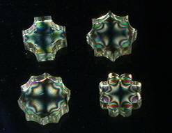
| Some materials turn birefringent when stressed. By
placing transparent materials between two polarizers, we can perform stress
analysis tests.
|
Stressed glass between crossed polarizers |