|
An optical wave guide is a structure that "guides" a light wave by constraining it to travel along a certain desired path. If the transverse dimensions of the guide are much larger than the wavelength of the guided light, then we can explain how the optical waveguide works using geometrical optics and total internal reflection (TIR). TIR occurs when light is incident on a dielectric interface at an angle greater than the critical angle θc. A wave guide traps light by surrounding a guiding region, called the core, made from a material with index of refraction ncore, with a material called the cladding, made from a material with index of refraction ncladding < ncore. Light entering is trapped as long as sinθ > ncladding/nncore. |
|
||||||||||||
| Light can be guided by planar or rectangular wave
guides, or by optical fibers.
An optical fiber consists of three concentric elements, the core, the cladding and the outer coating, often called the buffer. The core is usually made of glass or plastic. The core is the light-carrying portion of the fiber. The cladding surrounds the core. The cladding is made of a material with a slightly lower index of refraction than the core. This difference in the indices causes total internal reflection to occur at the core-cladding boundary along the length of the fiber. Light is transmitted down the fiber and does not escape through the sides of the fiber. |
 |
||||||||||||
|
|
||||||||||||
| Light injected into the fiber optic core and striking
the core-to-cladding interface at an angle greater than the critical
angle is reflected back into the core. Since the angles of
incidence and reflection are equal, the light ray continues to zigzag
down the length of the fiber. The light is trapped within the
core. Light striking the interface at less than the critical angle
passes into the cladding and is lost.
|
|
||||||||||||
| Problem: For 589nm light, calculate the critical angle for the following materials
surrounded by air.
Problem: An optical fiber is made of a clear plastic for which the index of refraction is 1.5. For what angles with the surface does light remain contained within the fiber?
Optical fibers usually are specified by their size. Usually the outer diameter of the core, the cladding and the buffer are specified. For example, 62.5/120/250 refers to a fiber with a 62.5 μm diameter core, a 120 μm diameter cladding and a 0.25 mm outer coating diameter. The laws governing the propagation of light in optical fibers are Maxwell’s equations. When information about the material constants, such as the refractive indices, and the boundary conditions for the cylindrical geometry of core and cladding is incorporated into the equations, they can be combined to produce a wave equation that can be solved for those electromagnetic field distributions that will propagate through the fiber. These allowed distributions of the electromagnetic field across the fiber are referred to as the modes of the fiber. They are similar to the modes found in microwave cavities and laser cavities. When the diameter of the core is large compared to the wavelength of the light propagating through the fiber, then the number of allowed modes becomes large and ray optics gives an adequate description of light propagation in fibers. Those fibers are called multimode fibers. |
|||||||||||||
| Fibers for which the refractive index of the core is a constant and the index changes abruptly at the core-cladding interface are called step-index fibers. Step-index fibers are available with core diameters of 100 to 1000 μm. They are well suited to applications requiring high-power densities, such as delivering laser power for medical and industrial applications. |
 |
||||||||||||
| For step-index fibers the fractional refractive
index difference is given by Δ = (ncore - ncladding)/ncore. The cone angle θcone of the cone of light that will be accepted by an optical fiber with a fractional index difference Δ is given by nisinθcone = (ncore2 - ncladding2)1/2 Here ni is the index of refraction of the material from which the light is entering the fiber. The numerical aperture (NA) is the measure of of how much light can be collected by an optical system. For a fiber, it is defined as ni times the sine of the maximum angle at which light rays can enter the fiber and be conducted down the fiber. It is given by NA = (ncore2 - ncladding2)1/2. When Δ << 1, this can be approximated by NA = ((ncore - ncladding)(ncore + ncladding))1/2 = (2ncore2Δ)1/2 = ncore(2Δ)1/2. The condition Δ << 1 is referred to as the weakly-guiding approximation. |
sinθc
= ncladding/ncore |
||||||||||||
| Multimode step-index fibers trap light with many
different entrance angles, each mode in a step-index multimode fiber is
associated with a different entrance angle. Each mode therefore
travels along a different path through the fiber. Different
propagating modes have different velocities. As an optical pulse
travels down a multimode fiber, the pulse begins to spread. Pulses
that enter well separated from each other will eventually overlap each
other. This limits the distance over which the fiber can transport
data. Multimode step-index fibers are not well suited for data
transport and communications. Bandwidth measures the data-carrying capacity of an optical fiber. It is expressed as the product of the data frequency and the distance over which data can be transmitted at that frequency. For example a fiber with a bandwidth of 400 MHz km can transmit data at a rate of 400 Mhz for 1 km or at a rate of 20 MHz for 20 km. Step-index fibers have a typical bandwidth of 20 MHz km. |
|
||||||||||||
| In a multimode graded-index fiber the core has
an index of refraction that decreases as the radial distance from the
center of the core increases. As a result, the light travels
faster near the edge of the core than near the center. Different
modes therefore travel in curved paths with nearly equal travel times.
This greatly reduces the spreading of optical pulses.
Graded-index fibers therefore have bandwidths which are significantly
greater than step-index fibers. Typical core diameters of graded-index fibers are 50, 62.5 and 100
μm. Graded-index fibers are often used in medium-range
communications applications, such as
local area networks. Graded-index fibers have a typical bandwidth of 500
MHz km at λ = 1300 nm and 160 MHz km at λ = 850 nm.
|
 |
||||||||||||
| A fan of rays injected into a graded-index fiber is brought back into focus,
before it diverges again. A ray will travel along an approximately
sinusoidal path. The wavelength of this sinusoidal path is called the pitch of the fiber.
The pitch is determined by Δ, the fractional index difference. If a graded-index fiber is cut to have a length of one quarter of
the pitch of the fiber, it can serve as an extremely compact lens, called a
GRIN
lens. Light exiting a fiber can be collimated into a parallel beam when the output end of the fiber is connected to the GRIN lens. Because its properties are set by its length, this graded-index lens is referred to as a quarter-pitch or 0.25 pitch lens. |
|
||||||||||||
| Focusing of the fiber output onto a small detector or focusing of the output of a source onto the core of a fiber can be accomplishing by increasing the length of the GRIN lens to 0.29 pitch. Then the source can be moved back from the lens and the transmitted light can be refocused at some point beyond the lens. Such an arrangement is useful for coupling sources to fibers and fibers to detectors. |
 |
||||||||||||
| The modes that propagate in a fiber are found by
solving Maxwell's equation for the electric field of
the light in the fiber in cylindrical coordinates. Solutions which are harmonic in space
and time, are of the form E(r,φ,z) = f(r) cos(ωt - βz + c) cos(qφ) where ω is the angular frequency of light and β is the propagation constant. Here z is the direction of propagation, and q is an integer. The group velocity of the mode is β/ω. It is important to make the distinction between the magnitude of the wave vector, k, and the magnitude of propagation constant β. In the ray approximation, β is the z-component of k. The normalized wave number, or V-number of a fiber is defined as V = kf a NA. Here kf, is the free space wave number, 2π/λ0, a is the radius of the core, and NA is the numerical aperture of the fiber. Many fiber parameters can be expressed in terms of V. For example, the number of guided modes n in a step-index multimode fiber is given by V2/2 for n >> 1, and a step index fiber becomes single-mode for a given wavelength when V < 2.405. In the weakly-guiding approximation (Δ << 1), the modes propagating in the fiber are linearly polarized (LP) modes characterized by two subscripts, m and n. The first subscript, m, gives the number of azimuthal, or angular nodes in the electric field distribution. The second subscript, n, gives the number of radial nodes. Output patterns are symmetric about the center of the beam and show bright regions separated by dark regions (the nodes that determine the order numbers m and n). The zero field at the outer edge of the field distribution is counted as a node. When the V number is less than 2.405 only the LP01 mode propagates. When the V number is greater than 2.405 the next linearly-polarized mode can be supported by the fiber, so that both the LP01 and LP11, modes will propagate. |
|
||||||||||||
| Multimode fibers used for telecommunications have V-numbers between ~50 or 150. A large number of modes are supported by these fibers. The amount of light carried by each mode is determined by the launch conditions. The attenuation of some large-angle modes is much higher than that of other modes, but after the light has propagated a considerable distance, a stable mode distribution develops. To generate a stable mode distribution even with only a short length of fiber, mode filtering is accomplished through mode scrambling. A series of bends is introduced into the fiber. These bends couple out the light in the large-angle modes with the high attenuation and distribute the remaining light among the other guided modes. Mode scrambling permits repeatable, accurate measurements of fiber attenuation to be made in the laboratory, even with short lengths of fiber. |
|
||||||||||||
| A single mode fiber only allows light to
propagate down its center and there are no longer different velocities
for different modes. A single mode fiber is much thinner than a
multimode fiber and can no longer be analyzed using geometrical optics.
Typical core diameters are between 5 and 10 μm.
Because the single-mode fiber propagates only the fundamental zero-order
mode, modal dispersion, the primary cause of pulse overlap, is
eliminated. Thus, the bandwidth of a single-mode fiber is much
higher than that of a multimode fiber. Pulses can be transmitted
much closer together in time without overlap. Because of this
higher bandwidth, single-mode fibers are used in all modern long-range
communication systems.
|
 |
||||||||||||
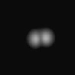
When laser light is coupled into a fiber, the distribution of the light emerging from the other end reveals if the fiber is a multimode or single mode fiber.
|
|
|
| Light emerging from a multi-mode fiber | Light emerging from a single-mode fiber |
Optical fibers are used widely in the medical field for diagnoses and treatment. Optical fibers can be bundled into flexible strands, which can be inserted into blood vessels, lungs and other parts of the body. An endoscope is a medical tool carrying two bundles of optic fibers inside one long tube. One bundle directs light at the tissue being tested, while the other bundle carries light reflected from the tissue, producing a detailed image. Endoscopes can be designed to look at regions of the human body, such as the knees, or other joints in the body.
Link: The endoscope
![]()
Signals lose strength as they propagate through the fiber. This is known as beam attenuation. Attenuation is measured in decibels (dB).
A(dB) = 10 log10(Pin/Pout) or 10(A/10) = Pin/Pout. Pout = 10-(A/10) Pin
Pin and Pout refer to the optical power going in and coming out of the fiber. The table below shows the power typically lost in a fiber for several values of attenuation in decibels.
| Attenuation (dB) | Power Loss (%) |
| 10 | 90 |
| 3 | 50 |
| 0.1 | 2 |
| Rayleigh Scattering — Microscopic-scale variations in the index of refraction of the core material can cause considerable scatter in the beam leading to substantial losses of optical power. | |
| Absorption — Current manufacturing methods have reduced absorption caused by impurities to very low levels. | |
| Bending — Manufacturing methods can produce minute bends in the fiber geometry. Sometimes these bends will be great enough to cause the light within the core to hit the core/cladding interface at less than the critical angle so that light is lost into the cladding material. This also can occur when the fiber is bent in a tight radius. Bend sensitivity is usually expressed in terms of dB/km loss for a particular bend radius and wavelength. |
Link: How are fibers made?