Light is a transverse electromagnetic wave. Diffraction, and interference are phenomena observed with all waves.
| Diffraction is the tendency of a
wave emitted from a finite source or passing through a finite aperture
to spread out as it propagates. Diffraction results from the
interference of an infinite number of waves emitted by a continuous
distribution of source points. According to
Huygens' principle
every point on a wave front of light can be considered to be a secondary
source of spherical wavelets. These
wavelets
propagate outward with the characteristic speed of
the wave. The wavelets emitted by all points on the wave front
interfere with each other to produce the traveling wave. Huygens'
principle also holds for electromagnetic waves. When studying the
propagation of light, we can replace any wave front by a collection of
sources distributed uniformly over the wave front, radiating in phase.
|
 |
| When light passes through a small
opening, comparable in size to the wavelength λ of the light, in an
otherwise opaque obstacle, the wave front on the other side of the
opening resembles the wave front shown on the right..
|
|
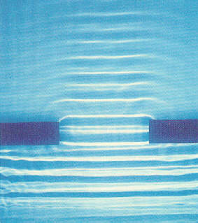
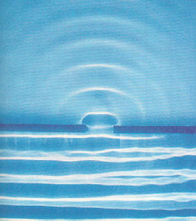
The light spreads around the edges of the obstacle. This is the phenomenon of diffraction. Diffraction is a wave phenomenon and is also observed with water waves in a ripple tank.
| Water waves in a ripple tank | |
A single large slit: |
A single small slit:
|
| When light passes through a single slit whose width w is on the order of the wavelength of the light, then we can observe a single slit diffraction pattern on a screen that is a distance L >> w away from the slit. The intensity is a function of angle. Huygens' principle tells us that each part of the slit can be thought of as an emitter of waves. All these waves interfere to produce the diffraction pattern. Where crest meets crest we have constructive interference and where crest meets trough we have destructive interference. |
 |
Very far from a point source the
wave fronts are essentially plane waves. This is called the
Fraunhofer regime,
and the diffraction pattern is called Fraunhofer diffraction. The
positions of all maxima and minima in the Fraunhofer diffraction pattern
from a single slit can be found from the following simple arguments.
|
|
| If the optical path length of two
rays differs by λ/2, the two rays interfere destructively. For ray 1 and
ray 7 to be half a wavelength out of phase we need
(w/2)sinθ = λ/2 or wsinθ = λ. But from geometry, if these two rays interfere destructively, so do rays 2 and 8, 3 and 8, and 6 and 10, 5 and 11, and 6 and 12. In effect, light from one half of the opening interferes destructively and cancels out light from the other half. Destructive interference produces the dark fringes. Dark fringes in the diffraction pattern of a single slit are found at angles θ for which w sinθ = mλ, where m is an integer, m = 1, 2, 3, ... . For the first dark fringe we have w sinθ = λ.
When w is smaller than λ , the equation wsinθ = λ has no solution and no dark fringes are produced. |
|
| If the interference pattern is
viewed on a screen a distance L from the slits, then the wavelength can
be found from the spacing of the fringes. We have λ = w sinθ/m and
sinθ = z/(L2 + z2)1/2), or
λ = zw/(m(L2 + z2)1/2), where z is the distance from the center of the interference pattern to the mth dark line in the pattern. If L >> z then (L2 + z2)1/2 ~ L and we can write λ = zw/(mL). |
 |
Problem:
When a monochromatic light source shines through a 0.2 mm wide slit onto a screen 3.5 m away, the first dark band in the pattern appears 9.1 mm from the center of the bright band. What is the wavelength of the light?
Link: Single slit diffraction II
Diffraction, and interference are phenomena observed with all waves.
| If light is incident onto an
obstacle which contains two very small slits a distance d apart, then
the wavelets emanating from each slit will interfere behind the
obstacle. Waves passing through each slit are diffracted and
spread out. At angles where the single slit diffraction
pattern produces nonzero intensity, the waves from the two slits can now
constructively or destructively interfere.
If we let the light fall onto a screen behind the obstacle, we will observe a pattern of bright and dark stripes on the screen, in the region where with a single slit we only observe a diffraction maximum. This pattern of bright and dark lines is known as an interference fringe pattern. The bright lines indicate constructive interference and the dark lines indicate destructive interference. The bright fringe in the middle of the diagram on the right is caused by constructive interference of the light from the two slits traveling the same distance to the screen. It is known as the zero-order fringe. Crest meets crest and trough meets trough. The dark fringes on either side of the zero-order fringe are caused by destructive interference. Light from one slit travels a distance that is ½ wavelength longer than the distance traveled by light from the other slit. Crests meet troughs at these locations. T he dark fringes are followed by the first-order fringes, one on each side of the zero-order fringe. Light from one slit travels a distance that is one wavelength longer than the distance traveled by light from the other slit to reach these positions. Crest again meets crest. |
 |
|
The diagram on the right shows the geometry for the fringe pattern. If light with wavelength λ passes through two slits separated by a distance d, we will observe constructively interference at certain angles. These angles are found by applying the condition for constructive interference, which is d sinθ = mλ, m = 0, 1, 2, … . The distances from the two slits to the screen differ by an integer number of wavelengths. Crest meets crest. The angles at which dark fringes occur can be found be applying the condition for destructive interference, which is d sinθ = (m+½)λ, m = 0, 1, 2, … . The distances from the two slits to the screen differ by an integer number of wavelengths + ½ wavelength. Crest meets trough. |
 |
If the interference pattern is viewed on a screen a distance L from the
slits, then the wavelength can be found from the spacing of the fringes.
We have sinθ = z/(L2 + z2)1/2 and λ = zd/(m(L2
+ z2)1/2), where z is the distance from the center of the
interference pattern to the mth bright line in the pattern.
If L >> z then (L2 + z2)1/2 ~ L and we can
write
λ = zd/(mL).
![]()
Link: Physics 2000: Wave Interference
| We have seen that diffraction
patterns can be produced by a single slit or by two slits.
When light encounters an entire
array of identical, equally-spaced slits, called a diffraction grating,
the bright fringes, which come from constructive interference
of the light waves from different slits, are found at the same angles
they are found if there are only two slits. But the pattern is
much sharper.
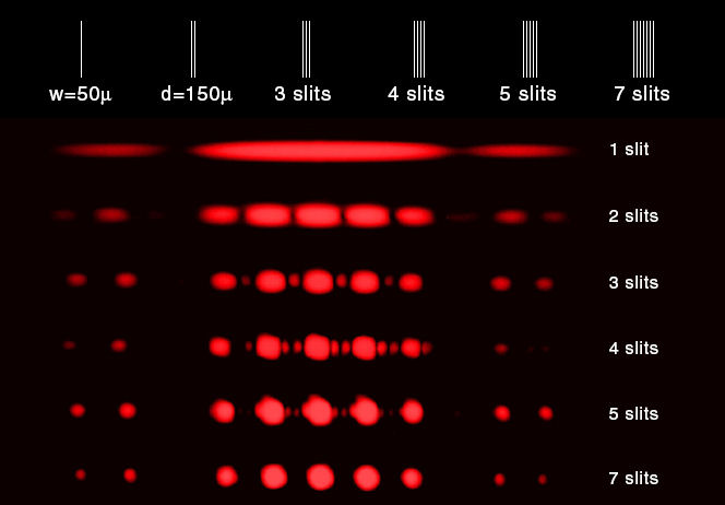
The figure on the right shows the interference pattern for various numbers of slits. The width of all slits is 50 micrometers and the spacing between all slits is 150 micrometers. The location of the maxima for two slits is also the location of the maxima for multiple slits. The single slit pattern acts as an envelope for the multiple slit patterns. Diffraction gratings contain a large number of parallel, closely spaced slits or grooves. They produce interference maxima at angles θ given by d sinθ = mλ. Because the spacing between the slits is generally very small, the angles θ are generally quite large. We cannot use the small angle approximation for relating wavelength and the position of the maxima on a screen for gratings, but have to use sinθ = z/(L2 + z2)1/2. |
 |
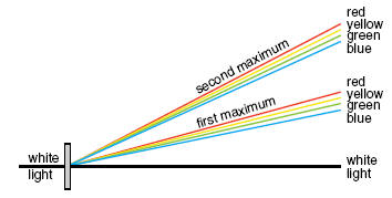
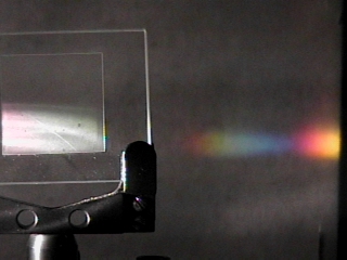
| Diffraction gratings disperse
white light into its component colors because different wavelengths
produce bright fringes at different angles.
d sinθ = mλ, The spectral pattern is repeated on either side of the main pattern. These repetitions are called "higher order spectra". There are often many of them, each one fainter than the previous one. If the distance between slits is d, and the angle to a bright fringe of a particular color is θ, the wavelength of the light can be calculated.
|
|
Problem:
The first order bright line appears 0.25 cm from the center bright line when a double slit grating is used. The distance between the slits is 0.5 mm and the screen is 2.7 m from the grating. Find the wavelength.
Problem:
A diffraction grating has 420 lines per mm. The grating is used to observe normally incident light with a wavelength of 440 nm. The grating is placed 1.3 m from a screen. Where on the screen will the first order bright line appear?
Diffraction patterns can be observed when light passes through a set of regularly spaced slits. For a diffraction to produce an observable pattern, the spacing of the slits must be comparable to the wavelength of the radiation. Visible light has a wavelength range from ~400 nm to ~700 nm. A typical diffraction grating for visible light with 300 grooves per mm has a slit spacing of (1/300)mm = 3 mm = 3000 nm. This spacing is 4 to 8 times larger than the wavelengths of visible light and produces an easily observable pattern.
The wavelengths of x-rays lie in the 1 nm to 1 pm range. A typical diffraction grating will not produce an observable pattern. But the wavelengths of x-rays are comparable to the spacing of atoms in common crystals, and material with a regularly spaced grid of atoms can diffract x-rays and produce diffraction patterns that can be captured on photographic film.