Problem 1:
In the below circuit, the switch has been closed for a long time before t =
0. The switch then opens at t = 0, and then closes at t = 100 μs. Find and plot vout(t).
Solution:
- Concepts:
Transient circuits, Thevenin equivalent circuits
- Reasoning:
We are asked to analyze the transient behavior of an RC circuit.
- Details of the calculation:
There are different approaches to analyzing this circuit, Kirchhoff's rules or
Thevenin equivalent circuits.
Use SI units, measure resistance in Ω, voltages in V and inductances in
H.
Let positive currents flow clockwise. Let I1 be the current
flowing through the battery, I2 be the current flowing through the
inductor
and I3 be the current flowing through the resistor on the right.
For t < 0 the inductor acts like a short circuit, the voltage across the
inductor vout = 0. The current flowing through the inductor is
0.1 A.
For 0 < t < 100 μs:
After the switch is opened the inductor and resistor on the
right form a simple RL circuit.
A current I2(0) = 0.1 A flows
counterclockwise in this circuit at t = 100 μs and decays exponentially with a
time constant τ = 1mH/100 Ω = 10 μs.
I2(0) = 0.1 A
exp(t/(10 μs)), I3(0) = -0.1 A exp(t/(10 μs)), using the sign
convention established above.
vout = I3 100 Ω = -10 V exp(t/(10 μs)).
At t = 100 μs we have vout = 4.54*10-4 V ≈ 0 ,
I2 = 4.54*10-6 A ≈ 0 .
(c) Using Kirchhoff's rules:
For t > 100 μs or t' = t - 100 μs > 0:
We can assume that no currents are flowing, vout = 0.
10 - 100 I1 - 100 I3 = 0.
LdI2/dt' - 100 I3 = 0.
I1 = I2 + I3.
Eliminate I1 from the first
equation:
10 - 100(I2 + I3) + 100 I3 = 0. I2
= 0.1 - 2 I3.
Use the second equation to eliminate I2:
2LdI3/dt' + 100 I3 = 0. dI3/dt = -5*104
I3.
I3 = I3(0)exp(-5*104 t').
Initial condition: I3(0) = 10/200 A = 0.05 A.
vout = I3100 V = 5 exp(-5*104 t') V.
The time constant for the circuit is 20 μs.
(ii) Using Thevenin equivalent circuits:
Consider the inductor to be the load, vout(t) = VL(t).
εeff
= (10 V) 100/200 = 5 V.
Zeff = 50 Ω. (We have 2 resistors in
parallel)
The equivalent circuit is just an simple Rl circuit.
vout(t')
= VL('t) = 5 exp(-Zefft'/L) V = 5 exp(-5*104 t')
V.
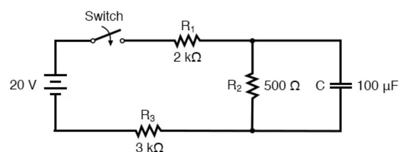
Problem 2:
In the below circuit, the switch has been open for a long time before t = 0.
The switch is then closed at t = 0. Find the voltage across the capacitor
at t = 60 ms.
Solution:
- Concepts:
Transient RC circuit
- Reasoning:
We are asked to analyze the transient behavior of an RC circuit.
- Details of the calculation:
There are different approaches to analyzing this circuit.
(i) Using Kirchhoff's rules:
Use SI units, measure resistance in Ω, voltages in V and C in Farad.
Let positive currents flow clockwise. Let I1 be the current
flowing through R1, I2 be the current flowing through R2
and I3 be the current flowing into the capacitor.
For t > 0 we have
20 - 5*103I1 - 5*102I2 = 0.
Q/C -
5*102I2 = 0.
I2 + I3 = I1. I3
= dQ/dt.
Eliminate I1 from the first
equation:
20 - 5000(I2 + I3) - 500I2
= 0. 20 - 5000I3
- 5500I2 = 0.
Use the second equation to eliminate I2:
I2 =
Q/(500C) = Q/(5*10-2).
20 - 5000I3
- 1.1*105Q = 0. I3 = 4*10-3 - 22Q = dQ/dt
Assume Q = A - Bexp(-t/x).
dQ/dt = B/x = -Q/x + A/x
x = 1/22, A =
4*10-3/22
Q(t) = 4*10-3/22 - Bexp(-22t).
Q(0) = 0, B = 4*10-3/2.2.
VC(t) = 1.82 V - 1.82 V
exp(-22t).
At t = 60 ms we have VC(60) = (1.82 V - 1.82 exp(-22*0.06)) V =
1.33 V.
(ii) Using Thevenin equivalent circuits:
εeff = VR2/(R1 + R2
+ R3) = 20*0.5/5.5 = 1.82.
Zeff = (R1 + R3)R2/(R1 + R2
+ R3) = 25*102/5.5.
The equivalent circuit is just an simple RC circuit.
VC(t) =
1.82V - 1.82 V exp(-t/0.0455).
Problem 3:
(a) The circuit shown below is at steady state. The input currents are
i1(t) = 10 cos(25 t) mA and i3(t) = 10
cos(25t + 135o) mA. Determine the voltage v2(t).
(b) The circuit shown below is at steady state. The inputs to this
circuit are the current source current i1(t) = 0.12 cos(100 t +
45o) A and the voltage source v2(t) = 24 cos(100 t - 60o)
V. Determine the current i2(t).
Solution:
- Concepts:
AC circuits. Kirchhoff's laws
- Reasoning:
All currents and voltages vary sinusoidaly
- Details of the calculation:
(a) i1(t) = I1eiωt, i2(t) = I2eiωt,
i3(t) = I3eiωt,v2(t) = V2eiωt.
I1 = 10, I3 = 10ei3π/4 = 10-2
cos(3π/4) + i10-2 sin(3π/4), ω = 25. (All quantities are in SI
units.)
Junction rule: I2 = I1 - I3 = 10-2(1
- cos(3π/4)) - i10-2 sin(3π/4) = 17.07*10-3 - i0.707*10-3
= 18.478*10-3 e-i0.393.
V2 = 250*I2 = 4.619e-i0.393. v2(t)
= 4.619 cos(25t - 22.5o).
(b) i1(t) = I1eiωt, i2(t)
= I2eiωt, i3(t) = I3eiωt,v2(t)
= V2eiωt.
I1 = 0.12eiπ/4, V2 = 24e-iπ/3 = 24
cos(π/3) - i24 sin(π/3), ω = 100. ( All quantities are in SI units.)
Junction rule: I2 = I1 - V2/96 =
0.12 cos(π/4) - 0.25 cos(π/3) + i[0.12 sin(π/4) - 0.25 sin(π/3)].
I2 = -0.04 - i0.301 = 0.304*ei1.703 = 0.304 cos(25t
+ (180 + 97.59)o)
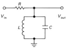
Problem 4:
Let Vin = Re(V0exp(iωt)). Derive an expression
for Vout/Vin as a function of frequency for the resonator
circuit below and determine the resonant frequency and the phase shift of Vout
at resonance from this expression.
Solution:
- Concepts:
AC circuits
- Reasoning:
We are asked to analyze an AC circuit.
- Details of the calculation:
Let V = V0eiωt.
I = Vin/Ztotal, Vout = IZLC
= VinZLC/Ztotal.
1/ZLC = 1/ZC + 1/ZL =
1/iωL + iωC = -i(1 - ω2LC)/(ωL).
ZLC = iωL/(1 - ω2LC).
Ztotal = R + ZLC, Ztotal/ZLC
= 1 + R/ZLC = 1 - iR(1 - ω2LC)/(ωL)
= [1 + (R/(ωL))2(1 - ω2LC)2]½exp(-iφ)
with tanφ = R(1 - ω2LC)/(ωL).
ZLC/Ztotal = ωL/[(ωL)2+ R2(1 - ω2LC)2]½exp(iφ).
Vout = VinωL exp(iφ)/[(ωL)2+ R2(1
- ω2LC)2]½.
|Vout| is maximum at resonance, when 1 - ω2LC = 0, ω2 =
1/(LC)½, f = 1/[2π(LC)½].
Then tanφ = 0, the phase shift is zero.
Vout = Vin at resonance. No current flows through
the resistor.