Problem 1:
Consider the circuit shown.
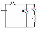
Let V = 50 V, R1 = 10 Ω, R2 = 100 Ω, and L = 50 H.
All circuit elements are ideal and no current flows before the switch is
closed.
(a) After the switch is closed at t = 0, find the current I flowing through
the switch as a function of time.
(b) After 8 s the switch is opened again. Right after the switch is opened,
what is the voltage across R2 and across the switch?
Solution:
- Concepts:
Transient RL circuits, Kirchhoff's rules
- Reasoning:
We are asked to analyze the transient behavior of an RL circuit.
- Details of the calculation:
(a) Let I1 flow through R1 and I2 flow through R2.
Assume the directions for I1 and I2 are from top to
bottom.
V - R1I1 - LdI1/dt = 0, V - I2R2
= 0, I = I1 + I2.
I2 = V/R2, dI1/dt = V/L - R1I1.
I1(t) = (V/R1)[1 - exp(-R1t/L)
I = 0.5 A + 5 A[1 - exp(-(0.2/s)t)].
(b) Right after the switch is opened I = 5 A[1 - exp[(-0.2/s)8 s)] = 4 A of
current flow through R2 from the bottom to the top. The voltage
across R2 is 400 V, Vbottom - Vtop = 400 V.
The voltage across the switch is 450 V.
Problem 2:
We connect a real inductor to a source of alternating voltage with an
amplitude of 10 V and a frequency of 60 Hz. A current with an amplitude of
16 mA flows through this circuit. The amplitude of the current drops to 12
mA when we connect a resistor with a resistance of 500 Ω in series with the
inductor. Find the inductance L and the resistance RL of the
inductor.
Solution:
- Concepts:
AC circuits
- Reasoning:
A real inductor has some resistance. We model it as an
ideal inductor L in series with a resistor RL.
For any series RL circuit we have
Z = R + iωL, |Z| = (R2 + ω2L2)½,
|I| = |V|/|Z|.
- Details of the calculation:
1.6*10-2 A = 10/(RL2 + ω2L2)½,
1.2*10-2 A = 10/((RL + 500 Ω)2 + ω2L2)½.
We have 2 equations for two unknowns.
In SI units:
RL2 + ω2L2 = (10/1.6*10-2)2
= 6252. ω2L2 = 6252 - RL2.
(RL + 500)2 + 6252 - RL2
= 1000 RL + 5002 + 6252 = 8332.
RL = 53.8 Ω.
ωL = 623 H/s, L = 1.65 H.
Problem 3:
In the circuit shown below, two conducting spheres of radius R each are
located far away from each other and are connected by thin wires through a
solenoid with inductance L. Initially, one of the spheres is charged and
the other is neutral. How long after the switch is closed do the charges
on the spheres become equal?
Solution:
- Concepts:
LC tank circuits
- Reasoning:
We treat the spheres as capacitors, each with Csp = 4πε0R.
The capacitors are in series (the connection is at infinity), so we have an LC tank
circuit with C = Csp/2 = 2πε0R.
The circuit is not
neutral, it carries an excess charge Q approximately uniformly distributed over the two
spheres. Denote the oscillating charge by Q' .
-
Details of the calculation:
Kirchhoff's loop rule:
Q'/C + LdI/dt = 0. d2Q'/dt2 + Q'/(LC) = 0. Q'
= (Q/2)cosωt, ω = (LC)-½.
Q/2 is the oscillating charge on the initially charged sphere.
The oscillation period is T = 2π/ω = 2π(LC)½ =
(2π)3/2(ε0RL)½
The charges on the spheres become equal for the first time after one quarter
period, T/4 = (π/2)(2πε0RL)½ .
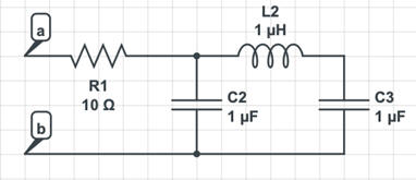
Problem 4:
(a) Calculate the total impedance between nodes (a) and (b) for an AC input V
= V0eiωt in symbolic form and using the given values
for R1, L2, C2, and C3?
(b) The current I flowing through R1 will vary sinusoidally.
I = I0ei(ωt+φ).
What happens to I0 when ω approaches the resonance frequency?
The resonance frequency of a complicated AC driven RLC circuit is the frequency
at which the impedance of the circuit is purely resistive. What happens when to I0 when ω is ~ 0.9 or 1.1 times the resonance
frequency?
Solution:
- Concepts:
AC circuits
- Reasoning:
We have a parallel RLC circuit with an AC generator, generating a sinusoidal
voltage.
- Details of the calculation:
(a)
Z = R1 + Z12. 1/Z12 = 1/Z1
+ 1/Z2. Z1 = -i/(ωC2), Z2
= iωL2 - i/(ωC3).
Z = R1 + Z1Z2/(Z1 + Z2) = R1 - i(L2ω2C3
- 1)/[ω(L2ω2C3C2 - C2 - C3)].
Here C2 = C3 = C, L2
= L, R1 =
R, therefore Z = R -
i(ω2LC - 1)/(ωC(ω2LC - 2)).
In SI units: Z = [10 - i(10-12ω2 - 1)/(ω10-6(10-12ω2
- 2))]Ω.
|Z| = [(10-12ω2 - 1)2 + 100]½/|ω10-6(10-12ω2
- 2)|.
(b) The resonance frequency of a complicated AC driven RLC
circuit is the frequency at which the impedance of the circuit is purely
resistive. This means that the reactance of the circuit is zero. At this
frequency, the voltage and current are in phase and the power factor is one.
Resonance frequency: 10-12ω2 - 1 = 0, ω = 106/s, Z = R = 10 Ω, I
= (V0/R)eiωt.
If ω = 0.9* 106/s, then Z = 10 - 0.177 i. |Z| =
10.0015.
I = (V0/|Z|)ei(ωt+φ). φ =
0.0177 = positive, the current leads the voltage.
If ω = 1.1*
106/s, then Z = 10 + 0.242 i. |Z| = 10.003.
I = (V0/|Z|)ei(ωt+φ). φ =
-0.021 = negative, the current lags the voltage.
As ω approaches the resonance frequency the current approaches is maximum
peak value and the phase angle φ approaches zero.
When ω is ~ 0.9 or 1.1 times the resonance frequency, the peak value of the
current is still very close to its maximum.
The phase angle is positive for 0.9 and negative for 1.1.
Aside:
This is complicated AC driven RLC circuit.
When ω --> 0, the capacitors become open circuits and I0
--> 0.
When ω --> ∞, the capacitors become short circuits and I0
--> V0/R1.
When ω = (2/(LC))½, the resonance frequency of the right loop
in the circuit, then |Z| = ∞ and I = 0.