Transients, RL circuits
Problem:
A 3 m long solenoid with a diameter of 0.05 m has 3000 turns of wire with total
resistance of 1 Ω uniformly wound along its length. It has an air
core.
(a) Find the approximate self-inductance of this solenoid.
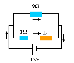
(b) If the solenoid and a 9 Ω resistor are
connected in parallel across the terminals of a 12 V battery, find the final
steady state current in the solenoid.
(c) If the battery is disconnected at time 0 leaving the circuit of the
solenoid and the resistor intact, find the current in the resistor as a function
of time.
(d) Show that the I2R losses in the resistor after
t = 0
is equal to the energy stored in the solenoid at t = 0.
Solution:
- Concepts:
Self inductance, Kirchhoff's rules, RL circuits
- Reasoning:
The coil, resistor and battery form an RL circuit, which can be analyzed
using Kirchhoff's rules.
- Details of the calculation:
(a) B = μ0nI = magnitude of B
inside the solenoid.
F = NBπR2 = LI = flux. L = Nμ0nπR2
= μ0n2πR2l,
l = length of solenoid, n = N/l.
L = (4π*10-7 N/A2)*(1000 m-1)2*π(0.025 m)2*3m
= 7.4*10-3 H.
(b) Is = 12 V/1 Ω = 12 A.
(c) LdI/dt + RI = 0. R = 10 Ω.
I = I0 exp(-Rt/L) = 12 A exp(-10 Ωt/(7.4*10-3 H))
= 12 A exp(-1351 t/s)
The current through the solenoid is decaying exponentially.
(d) P = I2R = 144 A2 exp(-2703 t/s)*10 Ω.
Energy dissipated = ∫0∞
P dt = 0.53 J.
Energy stored in solenoid at t = 0: E = ½LI2 =
½(7.4*10-3 H)(12 A)2 = 0.53 J.
Problem:
A solenoid of length l
= 1 m and cross-sectional area A = 1 cm2 has N = 10000 turns of wire
with a total resistance of 1 ohm. At t = 0 the solenoid is
connected to a V = 100 V power supply. Find the total work done by
the power supply in the time interval it takes for the current to increase from
zero to (1 - 1/e) = 0.6321 times its steady state value.
Give a numerical answer.
Solution:
- Concepts:
Induced emf, transient
- Reasoning:
As the current changes, an emf = -LdI/dt is induced. Here L is the
self-inductance of the solenoid.
- Details of the calculation:
Kirchhoff's loop rule yields
V = LdI/dt + IR, and I(t) = (V/R)(1 - exp(-(R/L)t).
The time it takes for the current to increase from zero to (1 - 1/e) times
its steady state value is found from
(1 - 1/e) = 1 - exp(-(R/L)t), t = L/R.
The power supplied by the battery is
P = VI = dW/dt.
The total work done in the time interval from t = 0 to t = L/R is
W = (V2/R) ∫0L/R(1 - exp(-(R/L)t)dt.
∫0L/R(1 - exp(-(R/L)t)dt = L/R - (L/R)(1 - 1/e).
W = LV2/R2 (1/e) = 0.3678 LV2/R2.
We can also write W = ½ LI2(t = L/R) + ∫0L/RI2(t)
R dt =
(L/2)(1 - 1/e)2(V2/R2) + (V2/R) ∫0L/R(1
- exp(-(R/L)t)2dt,
since the battery has to supply the energy dissipated in the resistance and
the energy stored in the magnetic field of the coil.
∫0L/R(1 - exp(-(R/L)t)2dt = ∫0L/R(1
- 2exp(-(R/L)t + exp(-(2R/L)t)dt
= L/R - 2(L/R)(1 - 1/e) + (L/2R)(1 - 1/e2) = (L/R)(2/e - 1/(2e2)
-½)
= (L/R)*0.168
W = 0.1998*LV2/R2 + 0.168*LV2/R2
= 0.3678 * LV2/R2.
The self-inductance of a solenoid is L = μ0N2A/l
.
For the given solenoid we therefore have L = 1.26*10-2 J/A2,
and V2/R2 = 104 A2.
We therefore have for the work W = 46.4 J.
Problem:
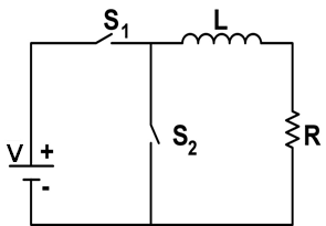
The circuit above is composed of a constant voltage source V, an inductor L, a
resistor R and two switches S1 and S2. Prior to time t =
0 both switches S1 and S2 are open.
(a) What is the current flowing through the inductor L immediately after S1
is closed at t = 0?
(b) What is the steady-state current flowing through the inductor L at a much
later time t1?
(c) At time t2 > t1 S2 is closed and S1
is opened at the same time. Write a differential equation and solve it to find
the current flowing through the inductor as a function of time .
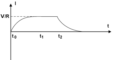
(d) Sketch
the current flowing through the in the inductor L, from time t = 0 until a time
much later than t2.
Solution:
- Concepts:
RL transient circuits
- Reasoning:
We are asked to analyze the transient behavior of an RL circuit.
- Details of the calculation:
(a) Immediately after S1
is closed the current through the inductor L is zero.
V - LdI/dt - RI = 0. dI/dt = -(R/L)I +V/L, I(t) = (V/R) (1 - exp(-Rt/L)).
(b) The steady state current through the inductor is I = V/R.
(c) LdI/dt + RI = 0
dI/I = (-R/L)dt, ∫ dI/I = -∫ (R/L)dt, ln(I) = (-R/L)t + C
At t = t2, the current is V/R, so ln(V/R) = (-R/L)t2 + C.
ln(I) = (-R/L)t + ln(V/R) + (R/L)t2
ln(RI/V) = (-R/L)(t - t2)
RI/V = e(-R/L)(t - t2)
I = (V/R)e-(t - t2)R/L for any t > t2
(d)
Problem:
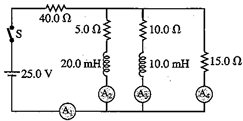
In the circuit shown in the figure, switch S is closed at time t = 0.
(a) Find the current reading of each meter just after S is closed.
(b) What does each meter read long after S is closed?
Solution:
- Concepts:
Transient in RL circuits
-
Reasoning:
At t = 0, the inductor acts like an open circuit, a long time after the switch
is closed the inductor acts like a short circuit.
-
Details of the calculation:
(a) A2 an A3 read zero, A1 an A4
read I = (25 V)/(55 Ω) = 0.45 A.
(b) Reff = (40 + 30/11) Ω = (470/11) Ω. Itotal =
V/Reff = 55/94 A =
0.585 A.
The voltage across the 5 Ω, 10 Ω, and 15 Ω resistors in parallel is 1.6 V.
I2 = 0.319 A, I3 = 0.16 A, I4 = 0.106 A,
A1 reads 0.585 A, A2 reads 0.319 A, A3
reads 0.16 A, A4 reads 0.106 A.
(a) Suppose a capacitor is charged by a voltage source, and then switched to a
resistor for discharging. Would a larger capacitance value result in a
slower discharge, or a faster discharge? How about a larger resistance value?
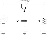
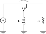
(b) Now consider an inductor, "charged" by a current source and then
switched to a resistor for discharging. Would a larger inductance value
result in a slower discharge, or a faster discharge? How about a larger
resistance value?
